
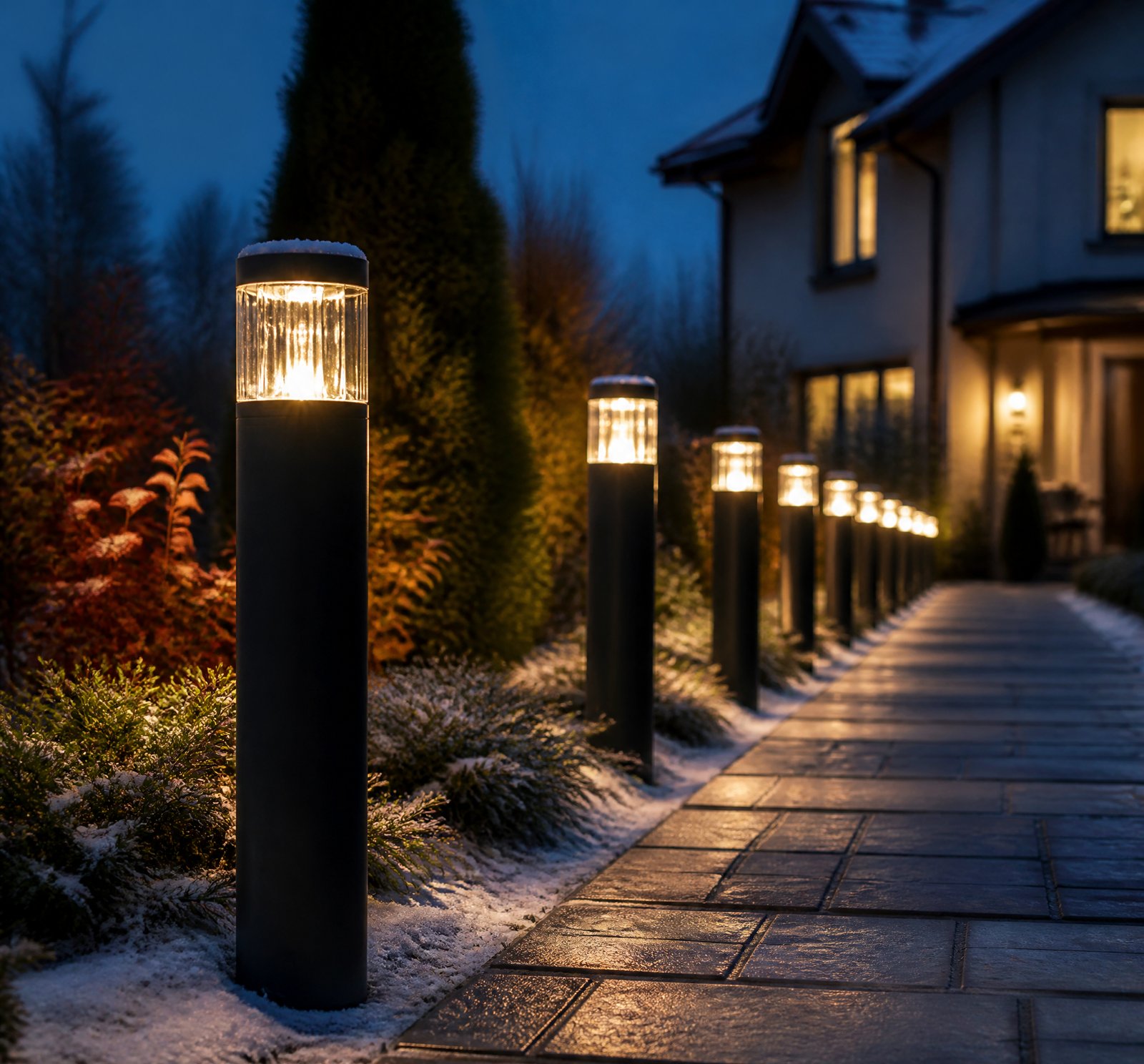
> Quick answer: Solar lamp manufacturers use accelerated aging protocols involving UV exposure, thermal cycling, and humidity stress to screen early failures before shipment [3][4][16][18]. These tests simulate real-world conditions but no universal duration or temperature profile is adopted industry-wide.
When it comes to solar lamps, ensuring they meet the durability standards expected by consumers is crucial. This article delves into the burn-in and aging protocols that manufacturers apply to screen for early failures before shipping their products. We will explore the importance of UV exposure, thermal cycling, and humidity stress in these tests.
Key Components of Burn-In Protocols
Solar lamps incorporate photovoltaic (PV) modules and LED lighting, making them susceptible to various environmental stresses. To ensure reliability, manufacturers use accelerated aging protocols that simulate long-term environmental conditions [1][4].
UV Exposure
One of the most critical aspects of these tests is UV exposure. Standards like ASTM D4329 outline practices for exposing materials to fluorescent UV lamps to evaluate their resistance to deterioration from light, heat, and moisture [4]. This type of testing helps identify potential degradation in both plastic enclosures and PV materials under real-world conditions.
Thermal Cycling
Thermal cycling is another essential component. High temperatures significantly impact LED lifespan by rapidly degrading light output until it reaches 50% of its initial value [11]. Therefore, thermal stress is a critical element in any aging test to ensure the product can withstand extreme temperature fluctuations.
Humidity Stress
Humidity stress tests are also vital as moisture ingress and connector degradation can lead to early failures, especially in high-humidity environments. These tests help manufacturers validate that their products meet durability standards [1][15].
Importance of UV Exposure
Recent studies suggest that UV exposure may be a more significant driver of long-term performance loss than previously thought [3][18]. High-efficiency cells designed to absorb UV light can degrade faster, making UV exposure a primary factor in degradation. This insight challenges the traditional assumption that thermal stress or mechanical fatigue is the main cause of failure.
Absence of Standardized Protocols
Despite the importance of these tests, there is no universally adopted burn-in duration or temperature profile for solar lamps [16]. While standards like ASTM D4329 provide exposure guidelines, they are not tailored to the full system (PV + LED + battery + controller). Therefore, protocols often vary by manufacturer and internal validation processes.
Key Takeaways
- UV Exposure: Is a critical factor in degradation and should be prioritized in burn-in tests [3][18].
- Thermal Cycling: Ensures products can withstand extreme temperature fluctuations [11].
- Humidity Stress: Prevents early failures due to moisture ingress and connector degradation [15].
Frequently Asked Questions
„`json
[
{
„q”: „Why is UV exposure crucial in burn-in tests?”,
„a”: „UV exposure simulates real-world conditions that cause material degradation. It is particularly important for modern solar cells designed to capture more UV light, which may degrade faster [3][18].”
},
{
„q”: „What are the key components of thermal cycling in burn-in protocols?”,
„a”: „Thermal cycling involves exposing the product to extreme temperature fluctuations. High temperatures can rapidly reduce LED lifespan by degrading light output [11].”
},
{
„q”: „How does humidity stress testing benefit solar lamp reliability?”,
„a”: „Humidity stress tests identify early failures due to moisture ingress and connector degradation, ensuring products meet durability standards in high-humidity environments [1][15].”
}
]
„`
References
- [1] PV_Connectors_Energy__075705d0 — authority
source passage
of some metals to high humidity and other environmental stressors; – Supply-chain pressures that lead to cost-cuts in manufacturing, including materials substitution and reduction; – Prevalence of low-quality replacement connectors that are vulnerable to ingress of moisture /and particulates. A Four-Part Investigation Our research spans these topic areas: Onsite inspections include visual inspections for evidence of cross-mating, separation or loose connections, and signs of heat deformation; and thermal inspection via a handheld long-wave infrared camera. Onsite data collection will include connector type, manufacturer and serial number, if known, location of connector in the array, and site metadata, including module make and model, system age, climate zone, exposure to extreme weather, etc. This task will also include development of a master spreadsheet to ensure thorough and consistent data across multiple sites. Connectors removed from photovoltaic systems as a result of onsite inspections, commercially off-the-shelf connectors and connectors obtained via the project’s mail-in program, will be subjected to materials characterization and forensics analysis. The COTS connectors will represent a statistically significant number of each type, based on such data as market share, unit price, morphology and country of origin, and will provide important data on the variation in quality of connectors being sold in the US. Techno-economic analysis (TEA) data will be collected in p
- [3] UNSW_Next-gen_solar_module_could_degrade_faster_than_expected__bfa0f162 — authority
source passage
you could expect depending on your location,” corresponding author Dr Poddar said. “It gives a holistic overview for manufacturers or developers who want to install panels somewhere, without having to do all the background calculations themselves.” The findings carry particular significance as the solar industry rapidly deploys advanced high-efficiency technologies designed to capture a broader portion of the solar spectrum, including ultraviolet light. While traditional silicon solar modules primarily rely on visible and infrared light to generate electricity, newer cell architectures such as TOPCon and heterojunction are engineered to harness UV radiation for improved conversion efficiency. That improvement, however, may come with unintended consequences for long-term reliability, with recent research documenting notable UV sensitivity in certain next-generation designs. “Our results highlight that modules with similar technology and orientation can still exhibit region-specific degradation,” the researchers state in the paper. “This is due to the influence of local weather and climate when exposed to outdoor conditions. This underscores the need for climate-specific indoor testing and accelerated tests for reliability and better lifetime predictions. “Notably, UV photodegradation alone can account for nearly a quarter of the total annual degradation in monocrystalline silicon modules in regions with high UV dose, potentially reducing system lifetime by seven to ten years.”
- [4] D4329_Standard_Practice_for_Fluorescent_Ultraviolet_UV_Lamp__c37a0ba9 — authority
source passage
# Standard Practice for Fluorescent Ultraviolet (UV) Lamp Apparatus Exposure of Plastics Source: Blog/Web URL: https://store.astm.org/d4329-21.html Author: Date: 2026-03-10 Standard Practice for Fluorescent Ultraviolet (UV) Lamp Apparatus Exposure of Plastics Significance and Use 4.1 The ability of a plastic material to resist deterioration caused by exposure to light, heat, and water is a property of significance in many applications. This practice is intended to induce property changes associated with end-use conditions, including the effects of ultraviolet solar irradiance, moisture, and heat. The exposure used in this practice is not intended to simulate the deterioration caused by localized weather phenomena, such as, atmospheric pollution, biological attack, and saltwater exposure. (Warning—Variation in operating conditions within the accepted limits of this practice will not necessarily provide the same results. Therefore, no reference to the use of this practice shall be made unless accompanied by a report prepared in accordance with Section that describes the specific operating conditions used. Refer to Practice for detailed information on the caveats applicable to use of results obtained in accordance with this practice.) Note 2: Additional information on sources of variability and on strategies for addressing variability in the design, execution, and data analysis of laboratory-accelerated exposure tests is found in Guide . 4.2 Reproducibility of test results betwe
- [11] Technologies_Archive_LED_professional_-_LED_Lighting_Technology__5c655d57 — authority
source passage
applications in general illumination, in projection and in the industrial sector. Read more » Technology | Jul 16, 2010 As we all know, the life span of an LED depends on the semi-conductor material used as well as the current/heat relationship. The light output of the LED becomes weaker and weaker and once it reaches 50% of its initial value, the life expectancy of the LED has, by definition, been reached. A life span of a few hundred and up to 100,000 hours is possible, but only when avoiding high temperatures which drastically reduce the length of the LED’s life. Read more » Technology | Jul 13, 2010 Organic light-emitting diodes (OLEDs) are currently a hot topic in the lighting industry. With major companies such as Osram, Philips, and General Electric displaying prototype products and announcing commercial availability of OLED panels for prototype lighting applications, it is difficult to ignore the industry buzz: “OLEDs are the future of lighting!” Read more » Technology | Dec 31, 1969 Numerous articles have been published regarding the lifetime of Light Emitting Diode (LED) luminaires, however, the primary focus has typically been on the lifetime of the LED die itself. Given that the LED luminaire is a system, it is important to recognize all aspects of the system that can affect or limit lifetime. Read more » Technology | Dec 31, 1969 Various new types of light emitting diodes (LEDs) are being developed and introduced for general illumination and other applications, a
- [15] PV_ModuleTech_2018_Light_optimisation_to_enhance_solar_-_PV_Tech__a5887bb4 — magazine
source passage
success in the display industry so we are using modelling to design a light redirecting structure and then we are also applying our long history of weathering science alongside material science to make sure that this material itself provides not just the immediate optical benefit but also the durability required to stay in the module for the 25-30 year lifetime expectancy. This morning at PV ModuleTech 2018, we've heard about lots of different failure modes, different degradation modes and we want to make sure this product is designed not to be the cause of that. There are so many other factors. We want to make sure that we are at least harnessing whatever light is coming in and directing it down on to the cell. After that its up to the module customers to make sure those electrons move properly, but we are going to make sure they get the solar energy to the spot on the module where it can be used. Are there any new products in the pipeline? Since we've launched in the market for two years, we've really proven the platform and the material set for long-term usage in the module, but there's other addressable spots in the module that are otherwise dead or unused. We have active programmes looking at additional ways to use our light management technology to continue increasing the power output of solar modules. We hope to be able to discuss those new products openly in the near future. What can module makers do to mitigate risk when they are releasing new types of module into th
- [16] The_sun_shines_every_day_-_Fraunhofer-Institut_für_Bauphysik_IBP__0a060f57 — authority
source passage
Thermal parameters – Climate simulation created a complex test model, featuring a total of six different climate zones in order to simulate real-life operation. Practical applications of the solar simulation Typical applications for solar simulation include accelerated aging of materials, determination of the total energy transmittance, clarification of functionality and service life or so-called thermal load tests, which are performed to examine the spontaneous failure of building components. In addition, emissions that condense as a bright-colored film in the intermediate space of building components, are also an issue. Regarding simulation, solar radiation is one of the most complex climatic elements. Besides determining the appropriate irradiance, also the spectra of the light sources and the optical components of the radiators need to be considered for each requirement. In the case of light-redirecting building components, for instance, relevant factors include the angle of incidence of solar radiation or the shares of direct and diffuse radiation, which depend on the time of day or the season. There are special test facilities for each field of application. When performing aging tests and thermal load tests on larger surfaces, mostly uncomplicated mixed-light sources are used. A 'radiant' test facility In the solar simulator, metal halide lamps are used, which emit a near-solar, continuous spectrum in the solar range from 300 to 2500 nm. "In our research work it is an e
- [18] UNSW_Next-gen_solar_module_could_degrade_faster_than_expected__bfa0f162 — authority
source passage
degradation rates of around 0.5 per cent per year, often assuming a steady, linear decline in performance. However, the UNSW study suggests that degradation may not follow a strictly linear pattern and that UV exposure could account for a significant fraction of total performance loss, particularly in high-irradiance environments where atmospheric conditions concentrate ultraviolet radiation on panel surfaces. “That number might not sound dramatic at first,” Dr Poddar said. “But when you quantify it over 20 years, it accumulates quite quickly.” The implications extend directly to project economics and warranty structures, particularly as previous UNSW research has shown that up to one-fifth of solar PV modules degrade 1.5 times faster than average. The team’s global UV mapping provides a mechanism to identify which geographic regions and mounting configurations face the highest risk of accelerated degradation, enabling more accurate financial modelling and warranty risk assessment before deployment. Testing standards lag behind field conditions Current international standards require solar modules to pass a UV test equivalent to 15 kilowatt-hours per square metre before receiving certification for deployment. This reaffirms some of the key messages UNSW scientists recently told PV Tech Premium regarding UV testing protocols for TOPCon cells. The UNSW research reveals a disconnect between this testing threshold and actual field conditions, particularly in high-irradiance regio
of some metals to high humidity and other environmental stressors; – Supply-chain pressures that lead to cost-cuts in manufacturing, including materials substitution and reduction; – Prevalence of low-quality replacement connectors that are vulnerable to ingress of moisture /and particulates. A Four-Part Investigation Our research spans these topic areas: Onsite inspections include visual inspections for evidence of cross-mating, separation or loose connections, and signs of heat deformation; and thermal inspection via a handheld long-wave infrared camera. Onsite data collection will include connector type, manufacturer and serial number, if known, location of connector in the array, and site metadata, including module make and model, system age, climate zone, exposure to extreme weather, etc. This task will also include development of a master spreadsheet to ensure thorough and consistent data across multiple sites. Connectors removed from photovoltaic systems as a result of onsite inspections, commercially off-the-shelf connectors and connectors obtained via the project’s mail-in program, will be subjected to materials characterization and forensics analysis. The COTS connectors will represent a statistically significant number of each type, based on such data as market share, unit price, morphology and country of origin, and will provide important data on the variation in quality of connectors being sold in the US. Techno-economic analysis (TEA) data will be collected in p
you could expect depending on your location,” corresponding author Dr Poddar said. “It gives a holistic overview for manufacturers or developers who want to install panels somewhere, without having to do all the background calculations themselves.” The findings carry particular significance as the solar industry rapidly deploys advanced high-efficiency technologies designed to capture a broader portion of the solar spectrum, including ultraviolet light. While traditional silicon solar modules primarily rely on visible and infrared light to generate electricity, newer cell architectures such as TOPCon and heterojunction are engineered to harness UV radiation for improved conversion efficiency. That improvement, however, may come with unintended consequences for long-term reliability, with recent research documenting notable UV sensitivity in certain next-generation designs. “Our results highlight that modules with similar technology and orientation can still exhibit region-specific degradation,” the researchers state in the paper. “This is due to the influence of local weather and climate when exposed to outdoor conditions. This underscores the need for climate-specific indoor testing and accelerated tests for reliability and better lifetime predictions. “Notably, UV photodegradation alone can account for nearly a quarter of the total annual degradation in monocrystalline silicon modules in regions with high UV dose, potentially reducing system lifetime by seven to ten years.”
# Standard Practice for Fluorescent Ultraviolet (UV) Lamp Apparatus Exposure of Plastics Source: Blog/Web URL: https://store.astm.org/d4329-21.html Author: Date: 2026-03-10 Standard Practice for Fluorescent Ultraviolet (UV) Lamp Apparatus Exposure of Plastics Significance and Use 4.1 The ability of a plastic material to resist deterioration caused by exposure to light, heat, and water is a property of significance in many applications. This practice is intended to induce property changes associated with end-use conditions, including the effects of ultraviolet solar irradiance, moisture, and heat. The exposure used in this practice is not intended to simulate the deterioration caused by localized weather phenomena, such as, atmospheric pollution, biological attack, and saltwater exposure. (Warning—Variation in operating conditions within the accepted limits of this practice will not necessarily provide the same results. Therefore, no reference to the use of this practice shall be made unless accompanied by a report prepared in accordance with Section that describes the specific operating conditions used. Refer to Practice for detailed information on the caveats applicable to use of results obtained in accordance with this practice.) Note 2: Additional information on sources of variability and on strategies for addressing variability in the design, execution, and data analysis of laboratory-accelerated exposure tests is found in Guide . 4.2 Reproducibility of test results betwe
applications in general illumination, in projection and in the industrial sector. Read more » Technology | Jul 16, 2010 As we all know, the life span of an LED depends on the semi-conductor material used as well as the current/heat relationship. The light output of the LED becomes weaker and weaker and once it reaches 50% of its initial value, the life expectancy of the LED has, by definition, been reached. A life span of a few hundred and up to 100,000 hours is possible, but only when avoiding high temperatures which drastically reduce the length of the LED’s life. Read more » Technology | Jul 13, 2010 Organic light-emitting diodes (OLEDs) are currently a hot topic in the lighting industry. With major companies such as Osram, Philips, and General Electric displaying prototype products and announcing commercial availability of OLED panels for prototype lighting applications, it is difficult to ignore the industry buzz: “OLEDs are the future of lighting!” Read more » Technology | Dec 31, 1969 Numerous articles have been published regarding the lifetime of Light Emitting Diode (LED) luminaires, however, the primary focus has typically been on the lifetime of the LED die itself. Given that the LED luminaire is a system, it is important to recognize all aspects of the system that can affect or limit lifetime. Read more » Technology | Dec 31, 1969 Various new types of light emitting diodes (LEDs) are being developed and introduced for general illumination and other applications, a
success in the display industry so we are using modelling to design a light redirecting structure and then we are also applying our long history of weathering science alongside material science to make sure that this material itself provides not just the immediate optical benefit but also the durability required to stay in the module for the 25-30 year lifetime expectancy. This morning at PV ModuleTech 2018, we've heard about lots of different failure modes, different degradation modes and we want to make sure this product is designed not to be the cause of that. There are so many other factors. We want to make sure that we are at least harnessing whatever light is coming in and directing it down on to the cell. After that its up to the module customers to make sure those electrons move properly, but we are going to make sure they get the solar energy to the spot on the module where it can be used. Are there any new products in the pipeline? Since we've launched in the market for two years, we've really proven the platform and the material set for long-term usage in the module, but there's other addressable spots in the module that are otherwise dead or unused. We have active programmes looking at additional ways to use our light management technology to continue increasing the power output of solar modules. We hope to be able to discuss those new products openly in the near future. What can module makers do to mitigate risk when they are releasing new types of module into th
Thermal parameters – Climate simulation created a complex test model, featuring a total of six different climate zones in order to simulate real-life operation. Practical applications of the solar simulation Typical applications for solar simulation include accelerated aging of materials, determination of the total energy transmittance, clarification of functionality and service life or so-called thermal load tests, which are performed to examine the spontaneous failure of building components. In addition, emissions that condense as a bright-colored film in the intermediate space of building components, are also an issue. Regarding simulation, solar radiation is one of the most complex climatic elements. Besides determining the appropriate irradiance, also the spectra of the light sources and the optical components of the radiators need to be considered for each requirement. In the case of light-redirecting building components, for instance, relevant factors include the angle of incidence of solar radiation or the shares of direct and diffuse radiation, which depend on the time of day or the season. There are special test facilities for each field of application. When performing aging tests and thermal load tests on larger surfaces, mostly uncomplicated mixed-light sources are used. A 'radiant' test facility In the solar simulator, metal halide lamps are used, which emit a near-solar, continuous spectrum in the solar range from 300 to 2500 nm. "In our research work it is an e
degradation rates of around 0.5 per cent per year, often assuming a steady, linear decline in performance. However, the UNSW study suggests that degradation may not follow a strictly linear pattern and that UV exposure could account for a significant fraction of total performance loss, particularly in high-irradiance environments where atmospheric conditions concentrate ultraviolet radiation on panel surfaces. “That number might not sound dramatic at first,” Dr Poddar said. “But when you quantify it over 20 years, it accumulates quite quickly.” The implications extend directly to project economics and warranty structures, particularly as previous UNSW research has shown that up to one-fifth of solar PV modules degrade 1.5 times faster than average. The team’s global UV mapping provides a mechanism to identify which geographic regions and mounting configurations face the highest risk of accelerated degradation, enabling more accurate financial modelling and warranty risk assessment before deployment. Testing standards lag behind field conditions Current international standards require solar modules to pass a UV test equivalent to 15 kilowatt-hours per square metre before receiving certification for deployment. This reaffirms some of the key messages UNSW scientists recently told PV Tech Premium regarding UV testing protocols for TOPCon cells. The UNSW research reveals a disconnect between this testing threshold and actual field conditions, particularly in high-irradiance regio