
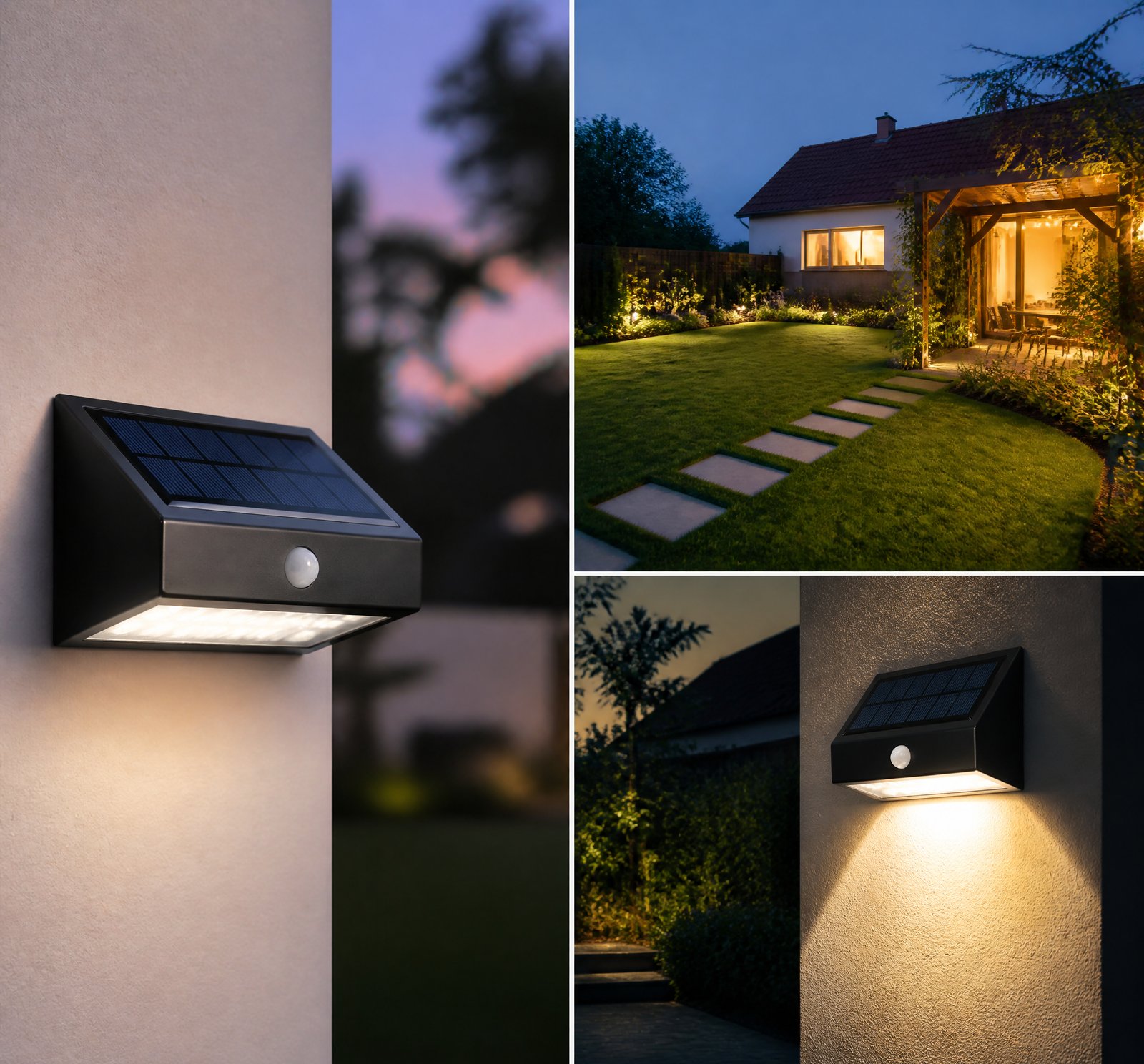
> Quick answer: Moisture intrusion in supposedly waterproof solar lamps occurs due to environmental factors like humidity, rainfall, and temperature fluctuations, which cause condensation and material stress [3][5]. Poor manufacturing quality, low-grade connectors, and inadequate maintenance further compromise seals, allowing water ingress despite IP ratings [1][20].
Solar lamps are widely used across Romania for outdoor lighting, offering sustainable, off-grid solutions. However, even those labeled “waterproof” often suffer from moisture intrusion—leading to corrosion, reduced efficiency, and early failure. This issue stems from real-world environmental challenges and technical limitations, not just poor design.
How Humidity and Temperature Fluctuations Cause Moisture Intrusion
High relative humidity accelerates corrosion on critical components like titanium-silver contacts in PV cells [3]. When combined with elevated temperatures, this degradation reduces conversion efficiency and shortens module lifespan [3]. Rainfall increases local humidity through evaporation, making panel surfaces sticky and prone to dust accumulation [3], which blocks sunlight and contributes to thermal stress. Rapid temperature changes cause materials to expand and contract, potentially cracking seals or solder bonds over time [5], creating pathways for moisture.
Manufacturing Defects and Material Compromises
Cost-cutting during production leads to the use of low-quality connectors and seals that fail under prolonged exposure [1]. These materials degrade faster in humid or wet conditions, undermining the lamp’s “waterproof” claims. Even IP-rated enclosures can fail if seals are improperly installed or made from inferior rubber or plastic [20].
Preventive Maintenance and Installation Best Practices
Regular cleaning—once every 1–2 weeks depending on soiling levels—prevents dust buildup that traps moisture and reduces efficiency [3]. During maintenance, inspect connectors, wiring, and seals for wear or cracks [20]. Proper installation matters too: south-facing orientation maximizes solar exposure in the Northern Hemisphere [24], while tilt angles help shed water and snow [11]. Ensure adequate drainage for grade-mounted units [16] and use tree-growth-compatible mounts to prevent branch-induced blockages [16].
Advanced Materials and Innovative Designs
Some solutions target the root causes using advanced materials. For example, silicone gels protect IGBT7 modules in inverters by maintaining flexibility and thermal stability through repeated heating and cooling cycles [13]. Similarly, patents describe adjustable solar lamps with repositionable collectors that optimize sun exposure while minimizing exposure to rain and snow [22]. These designs improve resilience without compromising efficiency.
Trade-offs in Alternative Moisture-Resistant Technologies
Electric discharge lamps with hydrophobic silicone coatings resist moisture film formation during humid weather, preventing starting voltage issues [19]. However, such coatings may increase opacity or cost compared to standard solar lamps [19]. While effective, they’re not always practical for large-scale outdoor lighting.
Comparison: Moisture-Resistant Solar Lighting Options
| Feature | Standard Solar Lamp | Hydrophobic Coated Lamp | Silicone Gel-Protected Inverter |
|——–|———————|————————–|——————————-|
| Moisture Resistance | Moderate (depends on seal quality) [1][20] | High (anti-film surface) [19] | Very High (thermal & flexible gel) [13] |
| Installation Complexity | Low | Medium | High |
| Cost | Low | Medium-High [19] | High |
| Durability in Wet Climates | Varies [3][5] | High [19] | Very High [13] |
Key Takeaways
Key Takeaways
- Humidity and temperature shifts cause condensation and material stress, leading to moisture intrusion even in waterproof lamps [3][5].
- Low-quality connectors and poor manufacturing compromise seals over time [1][20].
- Regular cleaning and proper installation (orientation, tilt, drainage) significantly reduce failure risks [3][16][24].
- Advanced materials like silicone gels offer long-term protection in harsh climates [13].
- Trade-offs exist: hydrophobic coatings improve moisture resistance but may reduce light output or increase cost [19].
References
- [1] PV_Connectors_Energy__075705d0 — authority
source passage
of some metals to high humidity and other environmental stressors; – Supply-chain pressures that lead to cost-cuts in manufacturing, including materials substitution and reduction; – Prevalence of low-quality replacement connectors that are vulnerable to ingress of moisture /and particulates. A Four-Part Investigation Our research spans these topic areas: Onsite inspections include visual inspections for evidence of cross-mating, separation or loose connections, and signs of heat deformation; and thermal inspection via a handheld long-wave infrared camera. Onsite data collection will include connector type, manufacturer and serial number, if known, location of connector in the array, and site metadata, including module make and model, system age, climate zone, exposure to extreme weather, etc. This task will also include development of a master spreadsheet to ensure thorough and consistent data across multiple sites. Connectors removed from photovoltaic systems as a result of onsite inspections, commercially off-the-shelf connectors and connectors obtained via the project’s mail-in program, will be subjected to materials characterization and forensics analysis. The COTS connectors will represent a statistically significant number of each type, based on such data as market share, unit price, morphology and country of origin, and will provide important data on the variation in quality of connectors being sold in the US. Techno-economic analysis (TEA) data will be collected in p
- [3] Photovoltaic Science, Engineering and Applications — book
source passage
dry periods. According to the studies in the literature, it is recommended to clean the PV panels once a week or every two weeks, depending on the rate of soiling amount. One negative effect of rainfall on the PV panel is related to relative humidity. In general, rainfall locally increases the relative humidity as a result of evaporation. The main effect of humidity on PV solar cells is corrosion. Naturally, higher temperatures and higher humidity levels accelerate the corrosion process. The corrosive effect mostly happens on the titanium-silver contact of PV cells in long-term humid environments. Increased relative humidity also causes the surface to become sticky, and accordingly collects dirt and dust on the surface of the PV panel. So, a sticky surface due to increased humidity levels results in drops in the conversion efficiency of modules. It has been proven that the relative humid- ity in the vicinity of PV sites causes degradation in PV cell current, voltage, power, and conversion efficiency. Although many studies are showing this effect in the literature, there is no generalized formulation for the humidity effect on different PV technologies. However, according to the stud- ies in the literature, the humidity effect on PV performance can be significant. For instance, a 50% decrease in cell efficiency can happen if relative humidity reaches from 60% to 95%. 4.8 SNOW AND ICING EFFECT ON PV SYSTEMS The existence of snow covering the PV modules can reduce the energy output
- [5] Off-Grid Solar_ A Bright Spot in the Global Energy Transition — book
source passage
can break down the protective layers of a solar panel, potentially leading to issues such as delamination or yellowing. 2. Temperature Fluctuations: Extreme temperature changes, especially rapid fluctuations, can cause solar panel materials to expand and contract. Over time, this constant change can lead to micro-cracks in the cells or damage to the solder bonds. 3. Moisture: If water infiltrates the panel due to a compromised seal or a defect, it can lead to corrosion of the metal contacts and connectors. Moisture intrusion can also cause the solar cells themselves to degrade at an accelerated rate. 4. Physical Stress: Events like hailstorms, wind-blown debris, or even the weight of snow can cause physical damage to panels. Such physical stressors can create micro-cracks or even break cells, leading to reduced efficiency. Detecting Panel Degradation Visual Inspection: One of the first signs of panel degradation is often visible damage. Discoloration, yellowing, or fogging within the panel can be signs of UV or moisture damage. Physical deformities like warping, delamination, or visible cracks are also indicative of degradation. Performance Monitoring: By consistently monitoring the energy output of a solar system, you can detect signs of degradation. If a system's output begins to decline outside of expected efficiency losses, it's an indication that one or more panels might be degrading at a faster rate. Using Electroluminescence Imaging: Professionals often use electrolumi
- [11] Photovoltaic Science, Engineering and Applications — book
source passage
an entire PV module. • The most significant factor affecting snowing energy loss is the tilt angle of the PV panel. As the tilt angle increases, the panel self-cleaning time decreases. For example, in an experimental study, the energy losses of a ° 40 tilted panel were found to be approximately 50% less than that of a ° 30 tilted panel for the snow covering less than one inch. 158 Photovoltaic Systems Engineering for Students and Professionals • Snow density could be a factor to compare the sites to each other. As known, the denser the snow, the more sunlight will get through the panel surface. Studies have shown that trans- mitted sunlight falls off exponentially through snow and ice. Typical sunlight transmission versus snow depth is plotted in Figure 4.11. • As the snow melts, its water content increases and causes a non-uniform snow density. The water-snow interface causes a greater degree of sunlight to scatter on the photovoltaic cells, generating heat as they absorb the solar radiation. Accordingly, this heat increases the amount of melted snow on the module surface. • Another important factor contributing to energy loss at the site is the cloudy days following heavy snow. Because, even if the ambient temperature is at freezing temperature, sunlight reaching the surface increases the cell temperature, which causes the surface snow to be melted. However, the panel does not receive enough sunlight to generate heat for melting the snow in cloudy situations. Consequently,
- [13] Advanced_silicone_gels_protect_IGBT7_modules_in_PV_inverters__ca968923 — magazine
source passage
gels also exhibit excellent thermal stability, the ability of a material to retain its physical properties when subjected to heat. Importantly, these gels maintain their flexibility and strength through repeated heating and cooling cycles, a common occurrence since solar power production and ambient temperatures increase during the day before power production stops and ambient temperatures fall at night. In power electronics like IGBT7 modules, thermal cycling is also important because load cycling and switching losses can cause temperatures to fluctuate significantly. Moisture resistance and high-voltage protection Advanced silicone gels resist moisture and contaminants that can cause short circuits or corrosion in electronics. When poured into an electronic enclosure, these gels encapsulate electronics and fill voids between IGBTs. Photovoltaic inverters are usually housed in metal or plastic cabinets, but poorly sealed doors, vents or cable entry points can allow the ingress of unwanted substances. Because PV enclosure cabinets are often located outdoors, the ingress of moisture and dust are concerns. These contaminants can also enter an enclosure during routine checks or maintenance activities. To help prevent contamination, PV enclosures are sealed using mechanical gaskets, but these seals are not enough. Ingress Protection (IP) standards describe the degree of protection that a sealed enclosure provides. Higher IP ratings denote greater levels of protection against wate
- [16] The IESNA lighting handbook_ A review — book
source passage
Electrical Code (NEC)" requirements. Luminaires should be suitable for wet locations. Make sure adequate drainage is provided for areas with grade-mounted luminaires. Wiring for downlights DW 21-14 EXTERIOR LIGHTING must be shielded from mechanical damage from the ground to 2.5 m (8 ft) above grade. Never aim downlights at an an- gle greater than 35° from vertical, or glare is likely to be a problem.'" Take advantage of the variety of shields offered by many manufacturers to control glare. Always use a mounting device that accommodates the growth of the tree. Plan and coordinate a maintenance and pruning schedule with the landscape architect or the landscape maintenance contractor."* Design Guidelines for Water Features Light interacts with water in three different ways: refraction, reflection, and dispersion (Figure 21-16). Light is refracted (changes direction) when passing from air into water or vice versa. This is why the apparent location of a submerged ob- ject can shift. Refraction also causes rainbows or sparkle in water droplets or in turbulent water. In addition to refraction, reflection also occurs when light strikes the water's surface; light is redirected back into the air or into the water in which it had been traveling. As with a mirror, the angle of incidence equals the angle of reflection. This is an important consideration for determining equip- ment location because it is possible to see luminaires as re- flected images in a pool. Reflection can also play a
- [19] Electric Discharge Lamps — book
source passage
3.11(b) and (c), and the specifications for starting voltages of lamps take account of this effect. One of the early problems that had to be solved in the development of fluorescent lamps was that of a continuous film of moisture on the surface of a lamp in a high-humidity atmosphere; this moisture film may have a surface resistance closely corresponding to that of the maximum start- ing voltage in Figure 3.11(a). On humid days in the summer, large numbers of lamps in an installation would simply fail to start. The problem was solved in this country by coating lamps with a hydrophobic silicone coating, which prevents moisture from forming a continuous film. In Europe, the preferred practice has been to include on the glass an internal conductive stripe of a sufficiently low resistance to ensure concentration of field at the electrodes. External conductive stripes have also been used. In general, these have not been preferred in this country because of their opacity (decrease in light output) and cost relative to the silicone coating system, which has worked quite satisfactorily. 70 IGNITION OR STARTING OF THE FLUORESCENT LAMP DISCHARGE References 1. L. B. Loeb, Basic Processes of Gaseous Electronics. Berkeley, Calif.: University of California Press, 1955, Chapter 8. 2. S. C. Brown, Basic Data of Plasma Physics. Cambridge, Mass.: M.I.T. Press, 1959, pp. 123 ff. 3. G. K. Wehner, “Sputtering by Ion Bombardment,” Advances in Elec- tronics and Electron Physics VII, L. Marton, ed.,
- [20] How_Does_Weather_Affect_PV_System_Degradation_and_Performance__c64c4d74 — authority
source passage
stresses. Researchers also warned that recent design trends like thinner cells, thinner front glass, and bigger modules may increase the likelihood of system vulnerability if not tested and designed correctly. Reviewing maintenance and operation records and monitoring PV assets would be a more proactive approach to detecting degradation among new module designs. NREL assembled a set of pre-storm checklists intended for utilities and independent power producers who own or operate solar PV installations. Depending on the system, electrical-specific steps generally require checking connectors, wiring, supports, and waterproofing. For example, in utility-scale ground-mounted systems, electrical staff should examine cable connections for corrosion, ensure the J-box is securely attached to the module, and check the grounding system for the tightness of connections and electrical continuity, among other considerations. It also suggests replacing parts like DC system wiring, cable materials, and enclosures. Waterproofing involves checking gaskets, conduit fittings, and seals to prevent wind-swept rain, then tightening or applying outdoor-rated sealant if necessary. Installing a weep hole in the bottom of the enclosure can also prevent moisture from escaping.
- [22] US9200767B2_-_Adjustable_solar_charged_lamp_-_Google_Patents__e3609d18 — patent
source passage
(AREA) – Photovoltaic Devices (AREA) – Testing Resistance To Weather, Investigating Materials By Mechanical Methods (AREA) Abstract An adjustable solar-charged lamp configured to collect and store energy from the sun and to illuminate the lamp with the stored energy, the lamp including a housing, a lens engaged with the housing; a solar collector attached to the housing; a battery and a light emitting device disposed within an interior of the housing and in communication with the solar collector; and a hanger assembly pivotally attached to the housing, wherein the solar collector is repositionable to the hanger assembly to provide maximum exposure to a light source, such as the sun. Description U.S. Provisional Patent Application No. 61/413,408 filed Nov. 13, 2010 Not Applicable Not Applicable In the past, location of a light source has been limited to locations with an available electrical connection. Examples of these traditional locations are offices, homes, schools, public sidewalks, etc. All of these examples are located where an electrical connection is readily available and attached to a larger electrical grid. Often, people do not have access to an electrical connection or the connection operates intermittently. Examples of non-electrified locations are modest dwellings, camping tents, outdoor gardens, rural areas, and countless other locations throughout the world. In the past, portable lamps have been developed to illuminate these non-electrified locations. Examples
- [24] Off-Grid Solar_ A Bright Spot in the Global Energy Transition — book
source passage
property will have the same solar potential. Buildings, trees, or other obstructions can cast shadows, seasonal changes can alter sun angles, and regional weather patterns can affect solar exposure. Key Factors in Identifying Solar Potential Solar Insolation: This is the amount of solar radiation received at a particular location. Measured in kWh/m^2/day, it gives a clear idea of how much sunlight a site gets. High insolation indicates more potential for solar energy generation. Orientation: The direction your panels face will significantly impact their energy output. In the Northern Hemisphere, south-facing installations generally receive the most sunlight. Tilt Angle: This refers to the angle at which panels are positioned relative to the ground. Ideally, this angle should be adjusted seasonally to match the sun's height in the sky. Shading: Even brief periods of shade can significantly reduce a solar panel's performance. It's crucial to ensure that the chosen site is free from obstructions like trees, buildings, or chimneys that might cast shadows. Assessment Tools and Techniques Solar Maps: Many regions now have solar maps, which can quickly give you a general idea of the solar potential in your area. These maps take into account historical weather data and average insolation values. Site Surveys: A thorough site survey involves an expert visiting your property to assess its solar potential. They'll check for shading obstructions, measure available space, and note the ori
of some metals to high humidity and other environmental stressors; – Supply-chain pressures that lead to cost-cuts in manufacturing, including materials substitution and reduction; – Prevalence of low-quality replacement connectors that are vulnerable to ingress of moisture /and particulates. A Four-Part Investigation Our research spans these topic areas: Onsite inspections include visual inspections for evidence of cross-mating, separation or loose connections, and signs of heat deformation; and thermal inspection via a handheld long-wave infrared camera. Onsite data collection will include connector type, manufacturer and serial number, if known, location of connector in the array, and site metadata, including module make and model, system age, climate zone, exposure to extreme weather, etc. This task will also include development of a master spreadsheet to ensure thorough and consistent data across multiple sites. Connectors removed from photovoltaic systems as a result of onsite inspections, commercially off-the-shelf connectors and connectors obtained via the project’s mail-in program, will be subjected to materials characterization and forensics analysis. The COTS connectors will represent a statistically significant number of each type, based on such data as market share, unit price, morphology and country of origin, and will provide important data on the variation in quality of connectors being sold in the US. Techno-economic analysis (TEA) data will be collected in p
dry periods. According to the studies in the literature, it is recommended to clean the PV panels once a week or every two weeks, depending on the rate of soiling amount. One negative effect of rainfall on the PV panel is related to relative humidity. In general, rainfall locally increases the relative humidity as a result of evaporation. The main effect of humidity on PV solar cells is corrosion. Naturally, higher temperatures and higher humidity levels accelerate the corrosion process. The corrosive effect mostly happens on the titanium-silver contact of PV cells in long-term humid environments. Increased relative humidity also causes the surface to become sticky, and accordingly collects dirt and dust on the surface of the PV panel. So, a sticky surface due to increased humidity levels results in drops in the conversion efficiency of modules. It has been proven that the relative humid- ity in the vicinity of PV sites causes degradation in PV cell current, voltage, power, and conversion efficiency. Although many studies are showing this effect in the literature, there is no generalized formulation for the humidity effect on different PV technologies. However, according to the stud- ies in the literature, the humidity effect on PV performance can be significant. For instance, a 50% decrease in cell efficiency can happen if relative humidity reaches from 60% to 95%. 4.8 SNOW AND ICING EFFECT ON PV SYSTEMS The existence of snow covering the PV modules can reduce the energy output
can break down the protective layers of a solar panel, potentially leading to issues such as delamination or yellowing. 2. Temperature Fluctuations: Extreme temperature changes, especially rapid fluctuations, can cause solar panel materials to expand and contract. Over time, this constant change can lead to micro-cracks in the cells or damage to the solder bonds. 3. Moisture: If water infiltrates the panel due to a compromised seal or a defect, it can lead to corrosion of the metal contacts and connectors. Moisture intrusion can also cause the solar cells themselves to degrade at an accelerated rate. 4. Physical Stress: Events like hailstorms, wind-blown debris, or even the weight of snow can cause physical damage to panels. Such physical stressors can create micro-cracks or even break cells, leading to reduced efficiency. Detecting Panel Degradation Visual Inspection: One of the first signs of panel degradation is often visible damage. Discoloration, yellowing, or fogging within the panel can be signs of UV or moisture damage. Physical deformities like warping, delamination, or visible cracks are also indicative of degradation. Performance Monitoring: By consistently monitoring the energy output of a solar system, you can detect signs of degradation. If a system's output begins to decline outside of expected efficiency losses, it's an indication that one or more panels might be degrading at a faster rate. Using Electroluminescence Imaging: Professionals often use electrolumi
an entire PV module. • The most significant factor affecting snowing energy loss is the tilt angle of the PV panel. As the tilt angle increases, the panel self-cleaning time decreases. For example, in an experimental study, the energy losses of a ° 40 tilted panel were found to be approximately 50% less than that of a ° 30 tilted panel for the snow covering less than one inch. 158 Photovoltaic Systems Engineering for Students and Professionals • Snow density could be a factor to compare the sites to each other. As known, the denser the snow, the more sunlight will get through the panel surface. Studies have shown that trans- mitted sunlight falls off exponentially through snow and ice. Typical sunlight transmission versus snow depth is plotted in Figure 4.11. • As the snow melts, its water content increases and causes a non-uniform snow density. The water-snow interface causes a greater degree of sunlight to scatter on the photovoltaic cells, generating heat as they absorb the solar radiation. Accordingly, this heat increases the amount of melted snow on the module surface. • Another important factor contributing to energy loss at the site is the cloudy days following heavy snow. Because, even if the ambient temperature is at freezing temperature, sunlight reaching the surface increases the cell temperature, which causes the surface snow to be melted. However, the panel does not receive enough sunlight to generate heat for melting the snow in cloudy situations. Consequently,
gels also exhibit excellent thermal stability, the ability of a material to retain its physical properties when subjected to heat. Importantly, these gels maintain their flexibility and strength through repeated heating and cooling cycles, a common occurrence since solar power production and ambient temperatures increase during the day before power production stops and ambient temperatures fall at night. In power electronics like IGBT7 modules, thermal cycling is also important because load cycling and switching losses can cause temperatures to fluctuate significantly. Moisture resistance and high-voltage protection Advanced silicone gels resist moisture and contaminants that can cause short circuits or corrosion in electronics. When poured into an electronic enclosure, these gels encapsulate electronics and fill voids between IGBTs. Photovoltaic inverters are usually housed in metal or plastic cabinets, but poorly sealed doors, vents or cable entry points can allow the ingress of unwanted substances. Because PV enclosure cabinets are often located outdoors, the ingress of moisture and dust are concerns. These contaminants can also enter an enclosure during routine checks or maintenance activities. To help prevent contamination, PV enclosures are sealed using mechanical gaskets, but these seals are not enough. Ingress Protection (IP) standards describe the degree of protection that a sealed enclosure provides. Higher IP ratings denote greater levels of protection against wate
Electrical Code (NEC)" requirements. Luminaires should be suitable for wet locations. Make sure adequate drainage is provided for areas with grade-mounted luminaires. Wiring for downlights DW 21-14 EXTERIOR LIGHTING must be shielded from mechanical damage from the ground to 2.5 m (8 ft) above grade. Never aim downlights at an an- gle greater than 35° from vertical, or glare is likely to be a problem.'" Take advantage of the variety of shields offered by many manufacturers to control glare. Always use a mounting device that accommodates the growth of the tree. Plan and coordinate a maintenance and pruning schedule with the landscape architect or the landscape maintenance contractor."* Design Guidelines for Water Features Light interacts with water in three different ways: refraction, reflection, and dispersion (Figure 21-16). Light is refracted (changes direction) when passing from air into water or vice versa. This is why the apparent location of a submerged ob- ject can shift. Refraction also causes rainbows or sparkle in water droplets or in turbulent water. In addition to refraction, reflection also occurs when light strikes the water's surface; light is redirected back into the air or into the water in which it had been traveling. As with a mirror, the angle of incidence equals the angle of reflection. This is an important consideration for determining equip- ment location because it is possible to see luminaires as re- flected images in a pool. Reflection can also play a
3.11(b) and (c), and the specifications for starting voltages of lamps take account of this effect. One of the early problems that had to be solved in the development of fluorescent lamps was that of a continuous film of moisture on the surface of a lamp in a high-humidity atmosphere; this moisture film may have a surface resistance closely corresponding to that of the maximum start- ing voltage in Figure 3.11(a). On humid days in the summer, large numbers of lamps in an installation would simply fail to start. The problem was solved in this country by coating lamps with a hydrophobic silicone coating, which prevents moisture from forming a continuous film. In Europe, the preferred practice has been to include on the glass an internal conductive stripe of a sufficiently low resistance to ensure concentration of field at the electrodes. External conductive stripes have also been used. In general, these have not been preferred in this country because of their opacity (decrease in light output) and cost relative to the silicone coating system, which has worked quite satisfactorily. 70 IGNITION OR STARTING OF THE FLUORESCENT LAMP DISCHARGE References 1. L. B. Loeb, Basic Processes of Gaseous Electronics. Berkeley, Calif.: University of California Press, 1955, Chapter 8. 2. S. C. Brown, Basic Data of Plasma Physics. Cambridge, Mass.: M.I.T. Press, 1959, pp. 123 ff. 3. G. K. Wehner, “Sputtering by Ion Bombardment,” Advances in Elec- tronics and Electron Physics VII, L. Marton, ed.,
stresses. Researchers also warned that recent design trends like thinner cells, thinner front glass, and bigger modules may increase the likelihood of system vulnerability if not tested and designed correctly. Reviewing maintenance and operation records and monitoring PV assets would be a more proactive approach to detecting degradation among new module designs. NREL assembled a set of pre-storm checklists intended for utilities and independent power producers who own or operate solar PV installations. Depending on the system, electrical-specific steps generally require checking connectors, wiring, supports, and waterproofing. For example, in utility-scale ground-mounted systems, electrical staff should examine cable connections for corrosion, ensure the J-box is securely attached to the module, and check the grounding system for the tightness of connections and electrical continuity, among other considerations. It also suggests replacing parts like DC system wiring, cable materials, and enclosures. Waterproofing involves checking gaskets, conduit fittings, and seals to prevent wind-swept rain, then tightening or applying outdoor-rated sealant if necessary. Installing a weep hole in the bottom of the enclosure can also prevent moisture from escaping.
(AREA) – Photovoltaic Devices (AREA) – Testing Resistance To Weather, Investigating Materials By Mechanical Methods (AREA) Abstract An adjustable solar-charged lamp configured to collect and store energy from the sun and to illuminate the lamp with the stored energy, the lamp including a housing, a lens engaged with the housing; a solar collector attached to the housing; a battery and a light emitting device disposed within an interior of the housing and in communication with the solar collector; and a hanger assembly pivotally attached to the housing, wherein the solar collector is repositionable to the hanger assembly to provide maximum exposure to a light source, such as the sun. Description U.S. Provisional Patent Application No. 61/413,408 filed Nov. 13, 2010 Not Applicable Not Applicable In the past, location of a light source has been limited to locations with an available electrical connection. Examples of these traditional locations are offices, homes, schools, public sidewalks, etc. All of these examples are located where an electrical connection is readily available and attached to a larger electrical grid. Often, people do not have access to an electrical connection or the connection operates intermittently. Examples of non-electrified locations are modest dwellings, camping tents, outdoor gardens, rural areas, and countless other locations throughout the world. In the past, portable lamps have been developed to illuminate these non-electrified locations. Examples
property will have the same solar potential. Buildings, trees, or other obstructions can cast shadows, seasonal changes can alter sun angles, and regional weather patterns can affect solar exposure. Key Factors in Identifying Solar Potential Solar Insolation: This is the amount of solar radiation received at a particular location. Measured in kWh/m^2/day, it gives a clear idea of how much sunlight a site gets. High insolation indicates more potential for solar energy generation. Orientation: The direction your panels face will significantly impact their energy output. In the Northern Hemisphere, south-facing installations generally receive the most sunlight. Tilt Angle: This refers to the angle at which panels are positioned relative to the ground. Ideally, this angle should be adjusted seasonally to match the sun's height in the sky. Shading: Even brief periods of shade can significantly reduce a solar panel's performance. It's crucial to ensure that the chosen site is free from obstructions like trees, buildings, or chimneys that might cast shadows. Assessment Tools and Techniques Solar Maps: Many regions now have solar maps, which can quickly give you a general idea of the solar potential in your area. These maps take into account historical weather data and average insolation values. Site Surveys: A thorough site survey involves an expert visiting your property to assess its solar potential. They'll check for shading obstructions, measure available space, and note the ori