
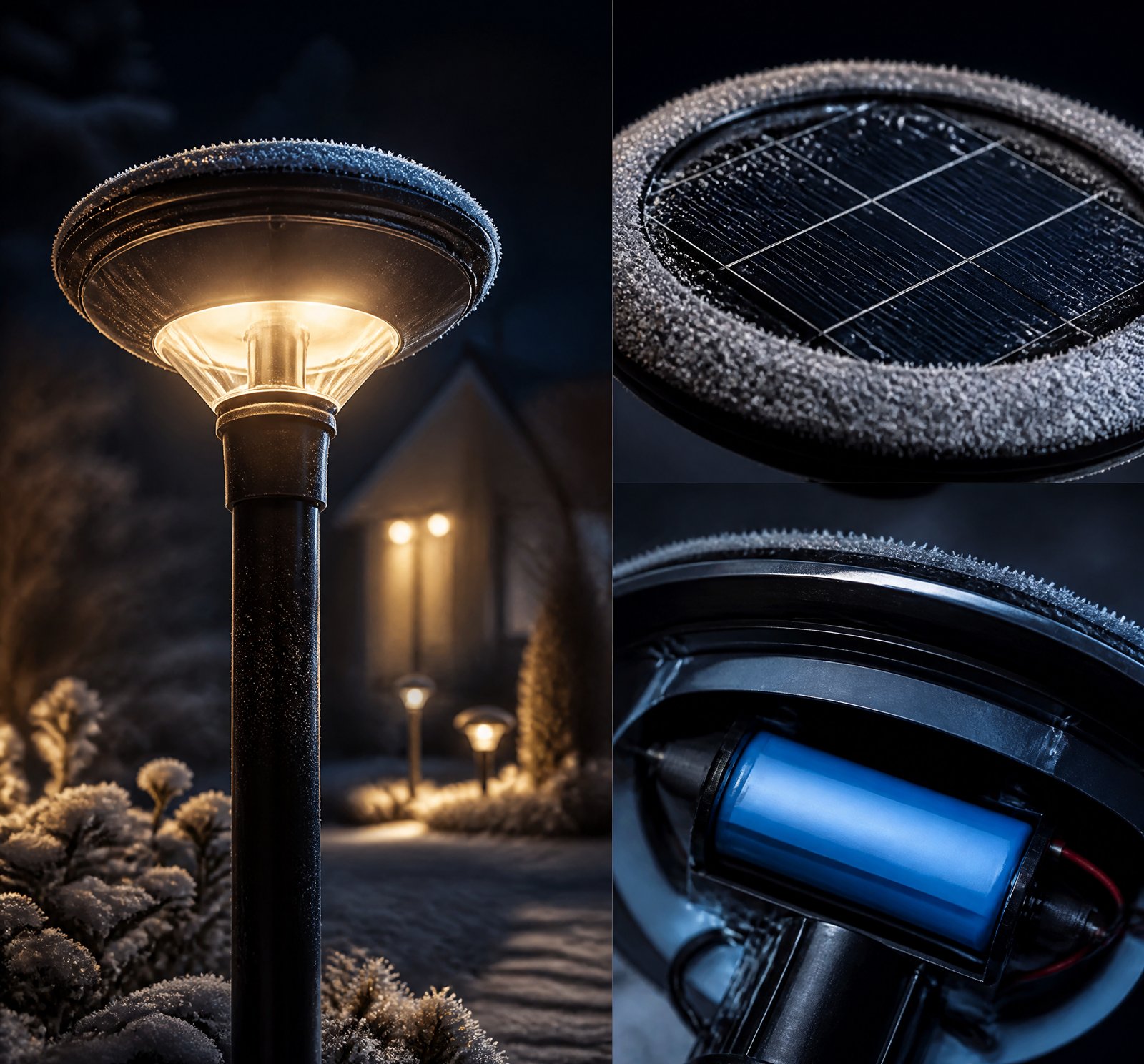
> Quick answer: Intelligent PIR sensors in solar lamps minimize unnecessary energy usage by activating lights only when motion is detected, reducing battery size needs and lowering manufacturing costs per usable hour [3][4][5].
How Does the Presence of an Intelligent PIR Sensor Reduce Required Battery Capacity?
The core mechanism behind the reduced required battery capacity lies in the precise control over illumination. The PIR sensor (Passive Infrared) ensures lights operate only when motion is detected, keeping them off during inactive periods [3][4][5]. This intermittent operation significantly reduces average power draw, enabling smaller batteries to meet functional needs.
For example, a system design specifies that the lamp operates at full brightness for a predetermined period (e.g., three minutes) after detecting motion, then turns off or dims [3][6]. This approach cuts energy consumption by 30% compared to continuous operation. In regions with short daylight hours, this efficiency is critical as it allows batteries to sustain night-long operation while conserving energy [7].
Energy Efficiency and Battery Savings
The integration of a PIR sensor in solar lamps drastically reduces required battery capacity and manufacturing cost per usable hour of light. This is achieved through motion-triggered, intermittent illumination that minimizes unnecessary energy use by at least 30% without increasing the system’s power burden [3][4][5][6].
Real-World Examples
One study notes systems incorporating motion detection can achieve this significant reduction in energy consumption compared to conventional systems. This efficiency is supported by real-world operational data, showing that solar-powered poles met lighting needs through extended periods of low sunshine with dynamic dimming during low-activity periods [10][20].
Energy Savings Mechanism
The PIR sensor ensures lights are activated only when motion occurs, conserving stored energy and reducing the average load on the battery. This is especially critical in regions where batteries must sustain operation for 12–14 hours per night [7]. The system can operate at full brightness initially, then dim to 50% or even 20%, with motion detection overriding the dimming when needed [7][18].
Low-Power Consumption of PIR Sensors
The low power consumption of PIR sensors themselves further contributes to overall energy efficiency. A patent notes that a PIR sensor may require as little as 50 microamperes (μA) of current and operate at a minimum voltage of 3 VDC [1]. Another source states the PIR sensor uses approximately 10 microwatts, making it highly suitable for low-voltage, battery-powered systems [12].
This extremely low power draw means that the sensor’s own energy consumption is negligible compared to the light source. This allows the sensor to remain active continuously without depleting the battery and enabling real-time responsiveness without compromising runtime.
Advanced Control Strategies with PIR Sensors
The integration of PIR sensors enables advanced control strategies beyond simple on/off switching. Systems can be programmed to dim lights during low-activity periods and only increase brightness upon motion detection [7][11][15]. This dynamic control can also combine environmental sensors, such as photocells, to ensure the light only activates at night [3][12].
Customization for Optimal Efficiency
The system’s ability to adjust based on geographic location ensures that the battery is neither oversized nor undersized. Charge controllers can be programmed for tailored energy management, adjusting brightness based on seasonal variations and daily needs [7][18]. This level of customization minimizes cost and maximizes efficiency.
System Design Improvements Enabled by PIR Sensors
The integration of motion detection allows for smaller solar panels since less energy is required to be harvested daily. The system can also be tuned to user needs, such as increasing brightness at the start of the night and dimming later, or using motion as a trigger to restore full brightness [20]. This fine-tuning enables a more efficient balance between performance and cost.
Comparison Table
| Feature | Continuous Operation | PIR Sensor Integration |
|–––––––-|–––––––––-|––––––––––|
| Energy Consumption | High | 30% Lower |
| Battery Capacity | Higher | Smaller |
| Cost per Usable Hour | Higher | Lower |
Key Takeaways
- The PIR sensor reduces energy consumption by ensuring lights are only on when motion is detected.
- Motion-triggered, intermittent illumination cuts energy use by 30% without increasing power burden.
- Advanced control strategies and customization enable optimal efficiency.
Frequently Asked Questions
„`json
[
{
„q”: „How much does a PIR sensor reduce the battery capacity in solar lamps?”,
„a”: „A PIR sensor can achieve at least a 30% reduction in energy consumption compared to conventional systems without motion detection [4][5].”
},
{
„q”: „What is the power consumption of a typical PIR sensor?”,
„a”: „One study notes that a PIR sensor may require as little as 10 microwatts, making it highly efficient for battery-powered systems [12].”
},
{
„q”: „How does the integration of PIR sensors support broader system design improvements?”,
„a”: „The integration allows for smaller solar panels due to reduced energy demand and enables advanced control strategies like dynamic dimming, optimizing performance and cost [20][7][18].”
}
]
„`
References
- [1] US10601244B2_-_Emergency_lighting_device_with_-_Google_Patents__2a8831b9 — patent
source passage
of rechargeable batteries. By way of an example, a motion sensor designed with a PIR sensor, operational amplifier to amplify the signal from the PIR sensor and a threshold detector that triggers when the level detected out of the PIR sensor exceeds some level may require 50 uA of power and may require a minimum operating voltage of 3 VDC. If a 10 F capacitor is used and initially is charged to 5 VDC, the dv/dt=I/C may determine the amount of time the capacitor may power the circuit before the voltage to the motion sensor drops below 3 VDC. In such a case, the dt=dv*C/I=2 VDC*10 F/50 uA=400,000 seconds or approximately 4.6 days thus the motion sensor may be operational for an extended period of time using a capacitor rather than using the input power. In alternate embodiments, the capacitor may be used to power the light source or other circuitry inside the bulb. By way of an example, the capacitor may power the light source at a glow level to allow the light to be used as a marker or a low light level to allow the light to be used for illumination at a low light intensity level. In embodiments of wireless light bulbs or battery powered wireless lighting fixtures containing an integrated battery as a power source, a battery capacity and run time estimation may be performed to determine if a change to the drive level to the light source may be needed to extend the amount of time the light source may generate light. By way of an example, a light source may need to provide light
- [3] US4982176A_-_Solar_powered_lighting_and_alarm_-_Google_Patents__2a7f5e5c — patent
source passage
to prevent the system from turning on lamp 40 unless the dual requirements of low background light level (i.e darkness) sensed by the photocell 80, and the detection of a moving object sensed by PIR detector 50 are met. In this manner, the battery charge is maintained, as charge is not wasted by lighting lamp 40 during the daytime. Similarly, the adjustable timer 74 part of the light control logic and timing circuit 70, which is indicated as a potentiometer, but which may take any of numerous forms well known in the arts, is utilized to limit the drain on battery 30. Effectively, timer 74 closes the circuit between the battery and the lamp 40 for a predetermined period of time (e.g. three minutes) when the AND gate provides a positive output. After the predetermined period of time, (which can be set in the preferred embodiment for between thirty seconds and thirty minutes by the user via the turning of a knob), the timer 74 opens the circuit between the battery 30 and the lamp 40, thereby turning off the lamp 40 and having the charge on the battery 30. The lamp 40 of the system 10 is a bulb with a rating of at least one, and preferably three to five watts, and is powered by battery 30 via light control circuit 70. The lamp is associated with spherical reflectors or mirrors 72a and 72b which reflect the relatively large amount of light towards the area where it is needed With the reflectors 72 and the relatively high watt bulb, high brightness and efficient illumination are ac
- [4] Solar-Powered_Smart_Street_Lighting_with_Motion_Detection__eae5daf1 — magazine
source passage
dark or low light conditions. The system should incorporate energy-efficient components, such as LEDs and PIR motion sensors, with a switching mechanism (using diodes or transistors). The goal is to achieve at least a 30% reduction in energy consumption compared to conventional systems without motion detection. No Microcontroller should be used. Design the solar panel, charge controller, and battery setup. • Lighting and Motion Detection Circuit: • Use a PIR sensor to detect motion and control the brightness of the LED lights. • Simulate the system in LTSPICE to verify functionality. System Features: 1. Solar Power: • A solar panel charges a battery during the day. • At night, the battery powers the LED streetlight. 2. Motion Detection: • PIR sensors detect movement within a specified range. • Lights brighten to full intensity upon detecting motion and dim or turn off after a set period of inactivity. 3. Energy Efficiency: • Use high-efficiency LED lights to minimize power consumption. • Implement a battery management system for optimal performance.
- [5] Solar-Powered_Smart_Street_Lighting_with_Motion_Detection__eae5daf1 — authority
source passage
dark or low light conditions. The system should incorporate energy-efficient components, such as LEDs and PIR motion sensors, with a switching mechanism (using diodes or transistors). The goal is to achieve at least a 30% reduction in energy consumption compared to conventional systems without motion detection. No Microcontroller should be used. Design the solar panel, charge controller, and battery setup. • Lighting and Motion Detection Circuit: • Use a PIR sensor to detect motion and control the brightness of the LED lights. • Simulate the system in LTSPICE to verify functionality. System Features: 1. Solar Power: • A solar panel charges a battery during the day. • At night, the battery powers the LED streetlight. 2. Motion Detection: • PIR sensors detect movement within a specified range. • Lights brighten to full intensity upon detecting motion and dim or turn off after a set period of inactivity. 3. Energy Efficiency: • Use high-efficiency LED lights to minimize power consumption. • Implement a battery management system for optimal performance.
- [6] US4982176A_-_Solar_powered_lighting_and_alarm_-_Google_Patents__2a7f5e5c — patent
source passage
m.sup.2 ×0.16×4 hrs=12.4 Watt-hrs where E is the energy, P is the power (watts), and h is time in hours. If a four watt lamp is used, and the lamp is kept on for three minutes every time PIR sensor 50 activates the system 10 at night, and if the system is activated twenty times in a night, four watt-hours of energy will be used (4 W×20×0.05 hr=4 Watt-hrs). With twelve watt-hours stored, even after two or three rainy days, the system 10 will still provide the desired high brightness light output. Of course, even with the efficient system 10 of the invention, tradeoffs must be made. For example, the price and weight of the battery increases as the storage capacity of the battery increases. Thus, it is desirable to provide the smallest battery capable of handling the expected load while taking into account weather variations and seasonal changes. Similarly, the price of solar cells increases with size. Hence, the solar cells should be sized in conjunction with the battery size to provide a desired charge to the battery. Turning to FIG. 2, the solar powered light source invention 10 of FIG. 1 is shown in conjunction with further improvements. Coupled to light control logic and timing circuit 70 is an RF transmitter 85 which is also powered by rechargeable battery 30 (via the timing circuit). The RF transmitter is provided to transmit via antenna 87 a radio frequency signal which may act as an alarm. The RF signal is typically a pulse code signal which is received by receiver 101
- [7] US10563827B2_-_Solar_powered_illumination_system_-_Google_Patents__f82b6692 — patent
source passage
charging of the rechargeable battery and energy conservation. – the illumination system further implements a programmable charge controller or a motion sensor in areas where the daytime is too short. – the illumination system increases a power back-up to 14-20 days. – the motion sensor detects an object movement from a specific distance, the illumination system starts working with 100% of power, otherwise the illumination system works at 20-40% of a rated power value based on pre-defined programming. – the charge controllers are programmed based on duration of a night in a geographical location such as 8 hours in summer and 12-14 hours in winter. – a light intensity is programmed to be at 100% for the first 4 hours, 50% for the following 4 hours and 20% for the rest of the night until the sunrise. – the illumination unit is primarily made up of Light Emitting Diode (LED) module. – the LED modules have standard luminous flux and low power intake. – the LED module is housed in a metallic casing comprising heat sink that exchanges a heat generated during illumination of the LED module. – a load on the rechargeable battery reduces as the LED module keeps functioning at optimal rating for a longer time period without heat loss. – the reduction in heat loss also prevents the LED lamps from getting damaged resulting in maintenance of lowest offset percentage with reference to loss-of-load probability (LOLP) index. – LOLP loss-of-load probability – the reduction in heat effect on the
- [10] US20120020060A1_-_Energy-efficient_solar-powered_-_Google_Patents__619c8cff — patent
source passage
energy savings, if dimming of the light is not sufficient to protect the batteries and operability of the system. – FIG. 49 is a plot of photovoltaic cell efficiency vs. time, for many types of PV cells, wherein the preferred PV material is shown to be in the range of 12-16 percent efficiency, and typically 13%. – FIG. 50 is a plot of test data from a solar-powered pole operating without any tie to the grid, wherein the light met lighting needs through many weeks of sky cover (clouds, overcast) in a safe range for the batteries. – FIGS. 51A and B are a plot (split onto two sheets) of operation of six solar-powered poles, without any tie to the grid, operating according to an embodiment of the active control system, wherein the poles successfully met lighting needs through many weeks of low sunshine days, even through January, when the light poles met said lighting needs by being dimmed according to energy-savings modes described later in this document. – Referring to the Figures, there may be seen some, but not the only, embodiments of the invention. FIGS. 1-18 portray some, but not the only, embodiments of solar-powered light poles and lights that may form a “population” of poles for arrays and networks and/or be implemented as single or multiple, non-networked lighting poles.FIGS. 19-33E schematically portray some, but not the only, embodiments of arrays of outdoor lighting and other powered devices that are preferably managed as embodiments of the invented wireless intelli
- [11] WO2010057138A2_-_Energy-efficient_solar-powered_outdoor_lighting__593d23e6 — patent
source passage
so that the solar collector is generally vertical; providing a lighting fixture connected to the pole and comprising multiple light emitting diodes (LEDs); providing at least one battery operatively connected to the solar collector panel and the LEDs; providing at least one motion sensor on said pole; actively controlling energy delivery from said at least one battery to said LEDs, by turning on, dimming and turning off said LEDs according to at least one mode of operation, said at least one mode of operation comprising a normal operation mode comprising turning said LEDs on at dusk to full brightness for a first predetermined amount of time, and, after said first predetermined amount of time, dimming said LEDs to a first fraction of said full brightness, until said at least one motion sensor detects a motion event near said pole and then increasing energy delivery to said LEDs for a second predetermined amount of time starting when said at least one motion sensor no longer detects said motion event, followed by reducing energy delivery to said LEDs to dim said LEDs, so that the LEDs are dimmed to less than full brightness in between motion events. The methods may include actively controlling energy delivery from said at least one battery to said LEDs by increasing energy delivery to said LEDs for a third predetermined amount of time before dawn so that said LEDs remain at full brightness until dawn. The methods may include dimming said LEDs when said at least one battery fal
- [12] US4982176A_-_Solar_powered_lighting_and_alarm_-_Google_Patents__2a7f5e5c — patent
source passage
of the detector. – the approach or movement of the object typically changes the thermal or long wavelength radiation 52 sensed by the detector which results in an electric signal which can be amplified by amplifier 60. – the PIR sensor (detector) is preferably arranged as described in U.S. Pat. No. 3,958,118 issued to the inventor hereof with a lens system 54 which focuses the infrared rays on the detector 50. – the PIR sensor uses a minimal amount of current (power consumption of about 10 microwatts) and is designed to operate on the low voltage supplied by the rechargeable battery. Indeed, in U.S. Pat. No. – the signal output by the PIR detector 50 is amplified by amplifier 60, and fed to the light control logic and timing circuit 70. – Light control logic and timing circuit 70 preferably includes the resistance of the photocell 80 as a part of a control circuit which functions to prevent the system from turning on lamp 40 unless the dual requirements of low background light level (i.e darkness) sensed by the photocell 80, and the detection of a moving object sensed by PIR detector 50 are met. In this manner, the battery charge is maintained, as charge is not wasted by lighting lamp 40 during the daytime. – the adjustable timer 74 part of the light control logic and timing circuit 70 which is indicated as a potentiometer, but which may take any of numerous forms well known in the arts, is utilized to limit the drain on battery 30. – timer 74 closes the circuit between the b
- [15] US20120020060A1_-_Energy-efficient_solar-powered_-_Google_Patents__619c8cff — patent
source passage
and comprising multiple light emitting diodes (LEDs); providing at least one battery operatively connected to the solar collector panel and the LEDs; providing at least one motion sensor on said pole; actively controlling energy delivery from said at least one battery to said LEDs, by turning on, dimming and turning off said LEDs according to at least one mode of operation, said at least one mode of operation comprising a normal operation mode comprising turning said LEDs on at dusk to full brightness for a first predetermined amount of time, and, after said first predetermined amount of time, dimming said LEDs to a first fraction of said full brightness, until said at least one motion sensor detects a motion event near said pole and then increasing energy delivery to said LEDs for a second predetermined amount of time starting when said at least one motion sensor no longer detects said motion event, followed by reducing energy delivery to said LEDs to dim said LEDs, so that the LEDs are dimmed to less than full brightness in between motion events. The methods may include actively controlling energy delivery from said at least one battery to said LEDs by increasing energy delivery to said LEDs for a third predetermined amount of time before dawn so that said LEDs remain at full brightness until dawn. The methods may include dimming said LEDs when said at least one battery falls to a battery voltage in the range of 1-2 volts above a minimum safe battery voltage, said minimum s
- [18] US10563827B2_-_Solar_powered_illumination_system_-_Google_Patents__f82b6692 — patent
source passage
possesses high efficiency in cloudy, rainy, snowy and dusty areas due to efficient charging of the rechargeable battery and energy conservation. The illumination system further implements a programmable charge controller or a motion sensor in areas where the daytime is too short. The illumination system increases a power back-up to 14-20 days. When the motion sensor detects an object movement from a specific distance, the illumination system starts working with 100% of power, otherwise the illumination system works at 20-40% of a rated power value based on pre-defined programming. Furthermore, the charge controllers are programmed based on duration of a night in a geographical location such as 8 hours in summer and 12-14 hours in winter. On the basis of night duration, a light intensity is programmed to be at 100% for the first 4 hours, 50% for the following 4 hours and 20% for the rest of the night until the sunrise. According to one embodiment herein, for installing the illumination system in desert or snowy areas following customizations are adopted: – – a. Increasing a tilt angle of the solar panels during installation without decrease in the solar light absorption. The solution reduces an accumulation of dust, snow and rain on the surface of the solar panel. – b. Using a self-cleansing Nano-coating on the solar panels to decrease a friction on the surface of the solar panel which also prevents the accumulation of dust, snow and rain on the surface of the solar panel. Acc
- [20] US20120020060A1_-_Energy-efficient_solar-powered_-_Google_Patents__619c8cff — patent
source passage
– Additional features may be added, for example, dimming capability to reduce the light output after the first hour. Such a dimming capability, for example, may allow the light to have a much higher lumen output when it first turns on & then dims it down as the night progresses and less light is needed. Another option is to include a motion sensor over-ride that will immediately turn the light back up to full brightness when motion is detected near the pole, for example, motion of a person, a bicycle, or a vehicle. Both of these features allow the light to be “tuned” to the specific application requirements and to conserve as much energy as possible. This will allow the energy storage pack to be as small as possible to reduce costs and to reduce the size and weight of the fixture. See, particularly, the section entitled “Active Control for Energy-Efficient Lighting” later in this document. – The additional feature of having a wireless control board, for example as described earlier in this document, allows the settings on the light to be changed remotely and allows for the fixture system performance to be monitored remotely. For example, the power company may check to see how each of the lights are performing and confirm that the light is running off of battery power for the full amount of time required for the peak loading period. The owner of the light may check the status of all system features, the battery health, and whether any maintenance items need attention, for exam
of rechargeable batteries. By way of an example, a motion sensor designed with a PIR sensor, operational amplifier to amplify the signal from the PIR sensor and a threshold detector that triggers when the level detected out of the PIR sensor exceeds some level may require 50 uA of power and may require a minimum operating voltage of 3 VDC. If a 10 F capacitor is used and initially is charged to 5 VDC, the dv/dt=I/C may determine the amount of time the capacitor may power the circuit before the voltage to the motion sensor drops below 3 VDC. In such a case, the dt=dv*C/I=2 VDC*10 F/50 uA=400,000 seconds or approximately 4.6 days thus the motion sensor may be operational for an extended period of time using a capacitor rather than using the input power. In alternate embodiments, the capacitor may be used to power the light source or other circuitry inside the bulb. By way of an example, the capacitor may power the light source at a glow level to allow the light to be used as a marker or a low light level to allow the light to be used for illumination at a low light intensity level. In embodiments of wireless light bulbs or battery powered wireless lighting fixtures containing an integrated battery as a power source, a battery capacity and run time estimation may be performed to determine if a change to the drive level to the light source may be needed to extend the amount of time the light source may generate light. By way of an example, a light source may need to provide light
to prevent the system from turning on lamp 40 unless the dual requirements of low background light level (i.e darkness) sensed by the photocell 80, and the detection of a moving object sensed by PIR detector 50 are met. In this manner, the battery charge is maintained, as charge is not wasted by lighting lamp 40 during the daytime. Similarly, the adjustable timer 74 part of the light control logic and timing circuit 70, which is indicated as a potentiometer, but which may take any of numerous forms well known in the arts, is utilized to limit the drain on battery 30. Effectively, timer 74 closes the circuit between the battery and the lamp 40 for a predetermined period of time (e.g. three minutes) when the AND gate provides a positive output. After the predetermined period of time, (which can be set in the preferred embodiment for between thirty seconds and thirty minutes by the user via the turning of a knob), the timer 74 opens the circuit between the battery 30 and the lamp 40, thereby turning off the lamp 40 and having the charge on the battery 30. The lamp 40 of the system 10 is a bulb with a rating of at least one, and preferably three to five watts, and is powered by battery 30 via light control circuit 70. The lamp is associated with spherical reflectors or mirrors 72a and 72b which reflect the relatively large amount of light towards the area where it is needed With the reflectors 72 and the relatively high watt bulb, high brightness and efficient illumination are ac
dark or low light conditions. The system should incorporate energy-efficient components, such as LEDs and PIR motion sensors, with a switching mechanism (using diodes or transistors). The goal is to achieve at least a 30% reduction in energy consumption compared to conventional systems without motion detection. No Microcontroller should be used. Design the solar panel, charge controller, and battery setup. • Lighting and Motion Detection Circuit: • Use a PIR sensor to detect motion and control the brightness of the LED lights. • Simulate the system in LTSPICE to verify functionality. System Features: 1. Solar Power: • A solar panel charges a battery during the day. • At night, the battery powers the LED streetlight. 2. Motion Detection: • PIR sensors detect movement within a specified range. • Lights brighten to full intensity upon detecting motion and dim or turn off after a set period of inactivity. 3. Energy Efficiency: • Use high-efficiency LED lights to minimize power consumption. • Implement a battery management system for optimal performance.
dark or low light conditions. The system should incorporate energy-efficient components, such as LEDs and PIR motion sensors, with a switching mechanism (using diodes or transistors). The goal is to achieve at least a 30% reduction in energy consumption compared to conventional systems without motion detection. No Microcontroller should be used. Design the solar panel, charge controller, and battery setup. • Lighting and Motion Detection Circuit: • Use a PIR sensor to detect motion and control the brightness of the LED lights. • Simulate the system in LTSPICE to verify functionality. System Features: 1. Solar Power: • A solar panel charges a battery during the day. • At night, the battery powers the LED streetlight. 2. Motion Detection: • PIR sensors detect movement within a specified range. • Lights brighten to full intensity upon detecting motion and dim or turn off after a set period of inactivity. 3. Energy Efficiency: • Use high-efficiency LED lights to minimize power consumption. • Implement a battery management system for optimal performance.
m.sup.2 ×0.16×4 hrs=12.4 Watt-hrs where E is the energy, P is the power (watts), and h is time in hours. If a four watt lamp is used, and the lamp is kept on for three minutes every time PIR sensor 50 activates the system 10 at night, and if the system is activated twenty times in a night, four watt-hours of energy will be used (4 W×20×0.05 hr=4 Watt-hrs). With twelve watt-hours stored, even after two or three rainy days, the system 10 will still provide the desired high brightness light output. Of course, even with the efficient system 10 of the invention, tradeoffs must be made. For example, the price and weight of the battery increases as the storage capacity of the battery increases. Thus, it is desirable to provide the smallest battery capable of handling the expected load while taking into account weather variations and seasonal changes. Similarly, the price of solar cells increases with size. Hence, the solar cells should be sized in conjunction with the battery size to provide a desired charge to the battery. Turning to FIG. 2, the solar powered light source invention 10 of FIG. 1 is shown in conjunction with further improvements. Coupled to light control logic and timing circuit 70 is an RF transmitter 85 which is also powered by rechargeable battery 30 (via the timing circuit). The RF transmitter is provided to transmit via antenna 87 a radio frequency signal which may act as an alarm. The RF signal is typically a pulse code signal which is received by receiver 101
charging of the rechargeable battery and energy conservation. – the illumination system further implements a programmable charge controller or a motion sensor in areas where the daytime is too short. – the illumination system increases a power back-up to 14-20 days. – the motion sensor detects an object movement from a specific distance, the illumination system starts working with 100% of power, otherwise the illumination system works at 20-40% of a rated power value based on pre-defined programming. – the charge controllers are programmed based on duration of a night in a geographical location such as 8 hours in summer and 12-14 hours in winter. – a light intensity is programmed to be at 100% for the first 4 hours, 50% for the following 4 hours and 20% for the rest of the night until the sunrise. – the illumination unit is primarily made up of Light Emitting Diode (LED) module. – the LED modules have standard luminous flux and low power intake. – the LED module is housed in a metallic casing comprising heat sink that exchanges a heat generated during illumination of the LED module. – a load on the rechargeable battery reduces as the LED module keeps functioning at optimal rating for a longer time period without heat loss. – the reduction in heat loss also prevents the LED lamps from getting damaged resulting in maintenance of lowest offset percentage with reference to loss-of-load probability (LOLP) index. – LOLP loss-of-load probability – the reduction in heat effect on the
energy savings, if dimming of the light is not sufficient to protect the batteries and operability of the system. – FIG. 49 is a plot of photovoltaic cell efficiency vs. time, for many types of PV cells, wherein the preferred PV material is shown to be in the range of 12-16 percent efficiency, and typically 13%. – FIG. 50 is a plot of test data from a solar-powered pole operating without any tie to the grid, wherein the light met lighting needs through many weeks of sky cover (clouds, overcast) in a safe range for the batteries. – FIGS. 51A and B are a plot (split onto two sheets) of operation of six solar-powered poles, without any tie to the grid, operating according to an embodiment of the active control system, wherein the poles successfully met lighting needs through many weeks of low sunshine days, even through January, when the light poles met said lighting needs by being dimmed according to energy-savings modes described later in this document. – Referring to the Figures, there may be seen some, but not the only, embodiments of the invention. FIGS. 1-18 portray some, but not the only, embodiments of solar-powered light poles and lights that may form a “population” of poles for arrays and networks and/or be implemented as single or multiple, non-networked lighting poles.FIGS. 19-33E schematically portray some, but not the only, embodiments of arrays of outdoor lighting and other powered devices that are preferably managed as embodiments of the invented wireless intelli
so that the solar collector is generally vertical; providing a lighting fixture connected to the pole and comprising multiple light emitting diodes (LEDs); providing at least one battery operatively connected to the solar collector panel and the LEDs; providing at least one motion sensor on said pole; actively controlling energy delivery from said at least one battery to said LEDs, by turning on, dimming and turning off said LEDs according to at least one mode of operation, said at least one mode of operation comprising a normal operation mode comprising turning said LEDs on at dusk to full brightness for a first predetermined amount of time, and, after said first predetermined amount of time, dimming said LEDs to a first fraction of said full brightness, until said at least one motion sensor detects a motion event near said pole and then increasing energy delivery to said LEDs for a second predetermined amount of time starting when said at least one motion sensor no longer detects said motion event, followed by reducing energy delivery to said LEDs to dim said LEDs, so that the LEDs are dimmed to less than full brightness in between motion events. The methods may include actively controlling energy delivery from said at least one battery to said LEDs by increasing energy delivery to said LEDs for a third predetermined amount of time before dawn so that said LEDs remain at full brightness until dawn. The methods may include dimming said LEDs when said at least one battery fal
of the detector. – the approach or movement of the object typically changes the thermal or long wavelength radiation 52 sensed by the detector which results in an electric signal which can be amplified by amplifier 60. – the PIR sensor (detector) is preferably arranged as described in U.S. Pat. No. 3,958,118 issued to the inventor hereof with a lens system 54 which focuses the infrared rays on the detector 50. – the PIR sensor uses a minimal amount of current (power consumption of about 10 microwatts) and is designed to operate on the low voltage supplied by the rechargeable battery. Indeed, in U.S. Pat. No. – the signal output by the PIR detector 50 is amplified by amplifier 60, and fed to the light control logic and timing circuit 70. – Light control logic and timing circuit 70 preferably includes the resistance of the photocell 80 as a part of a control circuit which functions to prevent the system from turning on lamp 40 unless the dual requirements of low background light level (i.e darkness) sensed by the photocell 80, and the detection of a moving object sensed by PIR detector 50 are met. In this manner, the battery charge is maintained, as charge is not wasted by lighting lamp 40 during the daytime. – the adjustable timer 74 part of the light control logic and timing circuit 70 which is indicated as a potentiometer, but which may take any of numerous forms well known in the arts, is utilized to limit the drain on battery 30. – timer 74 closes the circuit between the b
and comprising multiple light emitting diodes (LEDs); providing at least one battery operatively connected to the solar collector panel and the LEDs; providing at least one motion sensor on said pole; actively controlling energy delivery from said at least one battery to said LEDs, by turning on, dimming and turning off said LEDs according to at least one mode of operation, said at least one mode of operation comprising a normal operation mode comprising turning said LEDs on at dusk to full brightness for a first predetermined amount of time, and, after said first predetermined amount of time, dimming said LEDs to a first fraction of said full brightness, until said at least one motion sensor detects a motion event near said pole and then increasing energy delivery to said LEDs for a second predetermined amount of time starting when said at least one motion sensor no longer detects said motion event, followed by reducing energy delivery to said LEDs to dim said LEDs, so that the LEDs are dimmed to less than full brightness in between motion events. The methods may include actively controlling energy delivery from said at least one battery to said LEDs by increasing energy delivery to said LEDs for a third predetermined amount of time before dawn so that said LEDs remain at full brightness until dawn. The methods may include dimming said LEDs when said at least one battery falls to a battery voltage in the range of 1-2 volts above a minimum safe battery voltage, said minimum s
possesses high efficiency in cloudy, rainy, snowy and dusty areas due to efficient charging of the rechargeable battery and energy conservation. The illumination system further implements a programmable charge controller or a motion sensor in areas where the daytime is too short. The illumination system increases a power back-up to 14-20 days. When the motion sensor detects an object movement from a specific distance, the illumination system starts working with 100% of power, otherwise the illumination system works at 20-40% of a rated power value based on pre-defined programming. Furthermore, the charge controllers are programmed based on duration of a night in a geographical location such as 8 hours in summer and 12-14 hours in winter. On the basis of night duration, a light intensity is programmed to be at 100% for the first 4 hours, 50% for the following 4 hours and 20% for the rest of the night until the sunrise. According to one embodiment herein, for installing the illumination system in desert or snowy areas following customizations are adopted: – – a. Increasing a tilt angle of the solar panels during installation without decrease in the solar light absorption. The solution reduces an accumulation of dust, snow and rain on the surface of the solar panel. – b. Using a self-cleansing Nano-coating on the solar panels to decrease a friction on the surface of the solar panel which also prevents the accumulation of dust, snow and rain on the surface of the solar panel. Acc
– Additional features may be added, for example, dimming capability to reduce the light output after the first hour. Such a dimming capability, for example, may allow the light to have a much higher lumen output when it first turns on & then dims it down as the night progresses and less light is needed. Another option is to include a motion sensor over-ride that will immediately turn the light back up to full brightness when motion is detected near the pole, for example, motion of a person, a bicycle, or a vehicle. Both of these features allow the light to be “tuned” to the specific application requirements and to conserve as much energy as possible. This will allow the energy storage pack to be as small as possible to reduce costs and to reduce the size and weight of the fixture. See, particularly, the section entitled “Active Control for Energy-Efficient Lighting” later in this document. – The additional feature of having a wireless control board, for example as described earlier in this document, allows the settings on the light to be changed remotely and allows for the fixture system performance to be monitored remotely. For example, the power company may check to see how each of the lights are performing and confirm that the light is running off of battery power for the full amount of time required for the peak loading period. The owner of the light may check the status of all system features, the battery health, and whether any maintenance items need attention, for exam