
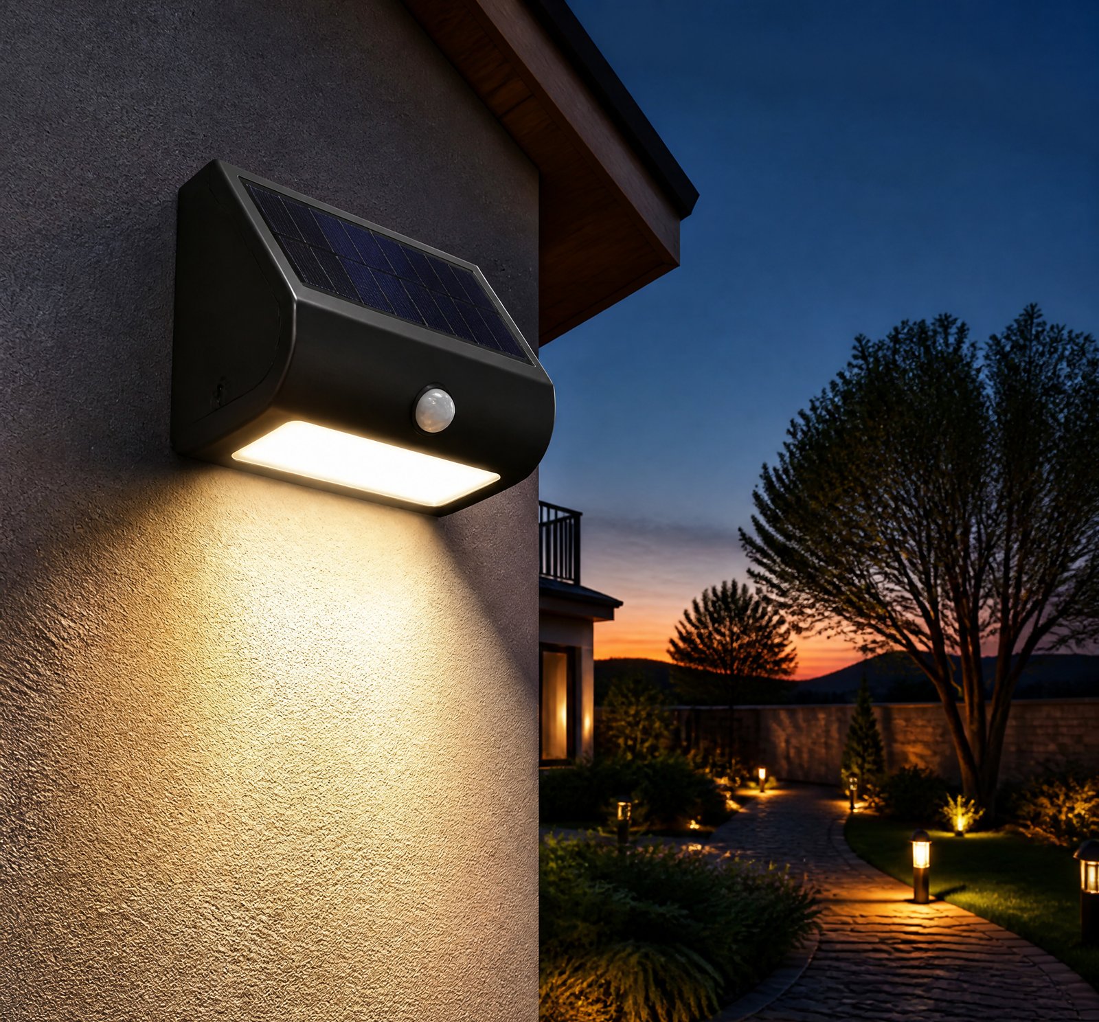
> Quick answer: The binning process ensures high-efficiency SMD LEDs have consistent color output at 6500K by sorting them based on chromaticity and spectral characteristics, minimizing green or magenta tints across batches [1][11].
The production of high-efficiency solar lamps relies on precise control over the LED manufacturing process to ensure consistent lighting quality. The binning process is a critical step in achieving this consistency, particularly for SMD LEDs operating at 6500K—considered cool or daylight white.
Understanding Binning in LED Manufacturing
Binning is a meticulous sorting method used in LED production to group individual LEDs with similar optical and electrical properties [1][11]. This process involves testing each LED for parameters such as forward voltage, luminous flux, and chromaticity coordinates. By grouping LEDs into batches with similar characteristics, manufacturers can ensure that the final product meets strict quality standards.
The Importance of Chromaticity Control
Chromaticity, or color consistency, is crucial in high-efficiency SMD LEDs to avoid perceptible tints such as green or magenta [5][24]. These tints arise from spectral imbalances that occur when using phosphor-converted white LEDs. Without proper binning, variations in the blue LED chip and yellow phosphor interactions can result in inconsistent color output across a production batch [18].
Addressing Color Mixing Concerns
Binning directly addresses customer concerns about perceptible differences between LEDs within the same bin. Improper binning can dramatically affect color mixing in multi-LED systems, leading to uneven lighting effects that are particularly noticeable in solar lamps or high-quality indoor applications [1][11]. By ensuring consistent chromaticity, manufacturers can deliver products with uniform lighting performance.
Challenges and Solutions in Binning
While the binning process is essential for maintaining color consistency, several challenges must be addressed:
The Role of Spectrometers
Advanced tools such as spectrometers are used to measure chromaticity coordinates, peak wavelengths, and spectral power distributions. These measurements enable precise sorting into bins that meet target color temperatures like 6500K [22][25].
Thermal Stability Considerations
LED performance is sensitive to temperature changes, with emission power decaying exponentially as the temperature rises [3][9]. This thermal dependence can cause significant color shifts over time. Manufacturers must ensure proper binning and implement robust thermal management to maintain spectral stability in outdoor or high-heat environments like solar lamps.
Long-Term Performance
To guarantee long-term reliability, rigorous testing protocols are necessary. For instance, Philips grow lights are designed to maintain 95% of their initial light output after 36,000 hours with minimal spectral change [13]. This underscores the importance of both binning and design in ensuring consistent performance.
Comparison Table: Binning vs. Dynamic Current Control
| Method | Description | Advantages |
|–––––––|––––––––––––––––––|––––––––––––––|
| Binning | Sorting LEDs based on chromaticity and spectral output [1][11] | Ensures initial color consistency |
| Dynamic Current Control | Real-time monitoring and adjustment of LED power | Maintains long-term stability over time |
Future Directions: Perovskite LEDs
The development of perovskite LEDs, which can be tuned to emit specific colors by altering atomic composition, offers a promising path toward more consistent light sources [20]. While not currently used in solar lamps, these advancements could reduce the need for complex binning processes.
Key Takeaways
- Binning involves precise sorting based on chromaticity and spectral output to ensure LED consistency.
- Spectrometers are crucial tools for accurate measurement and sorting during the binning process [22][25].
- Thermal management is essential for maintaining long-term color stability in outdoor applications like solar lamps.
References
- [1] Japan_sets_white_LED_targets_as_technology_improves_-_News__58fe3a46 — magazine
source passage
that allows metrics such as CRI to be calculated for different LED types – for example by altering the wavelengths of the individual LEDs in an RGB combination. He demonstrated that a well designed RGB LED can give good color rendering, while a 4-chip device has an excellent CRI value. However, the deficiencies inherent in the CRI mean that a new metric needs to be devised for the LED industry. Kevin Dowling of lighting-system designer Color Kinetics discussed how color is perceived by the human eye, and the issues that are peculiar to using LEDs. The human eye has a huge dynamic range but also has a nonlinear response to luminance. Small changes are very noticeable at low brightness levels, but much larger changes can be tolerated at high brightness. One issue for LED lifetime, which is defined by lumen depreciation, is whether or not the change in lumen output can actually be observed by the user. Other light sources also depreciate, but for these there tend to be different ways of defining lifetime. Another issue is color consistency between LEDs: "Customers can perceive differences and they care," said Dowling, whose company manufactures LED-based lighting systems. "It is sometimes possible to perceive differences between LEDs in the same bin, and color mixing can be dramatically affected by improper binning." Noting that the different LED manufacturers have different ways of binning their products, Dowling raised the question of the need for standardization in this area.
- [3] Light-emitting_diode_-_Wikipedia__ba8713f3 — wikipedia
source passage
the devices warm up. If forward voltage binning is not possible, a circuit is required to ensure even distribution of current between parallel strands.[83] – Slow failure: LEDs mainly fail by dimming over time, rather than the abrupt failure of incandescent bulbs.[84] – Lifetime: LEDs can have a relatively long useful life. One report estimates 35,000 to 50,000 hours of useful life for white LEDs, though time to complete failure may be shorter or longer.[85] Fluorescent tubes typically are rated at about 10,000 to 25,000 hours, depending partly on the conditions of use, and incandescent light bulbs at 1,000 to 2,000 hours. Several DOE demonstrations have shown that reduced maintenance costs from this extended lifetime, rather than energy savings, is the primary factor in determining the payback period for an LED product.[86] – Cycling: LEDs are ideal for uses subject to frequent on-off cycling, unlike incandescent and fluorescent lamps that fail faster when cycled often, or high-intensity discharge lamps (HID lamps) that require a long time to warm up to full output and to cool down before they can be lighted again if they are being restarted. – Temperature dependence: LED performance largely depends on the ambient temperature of the operating environment – or thermal management properties. Overdriving an LED in high ambient temperatures may result in overheating the LED package, eventually leading to device failure. An adequate heat sink is needed to maintain long life. This
- [5] LED_Lighting_in_Museums_and_Art_Galleries_Technical_-_Canadaca__7f9b6307 — authority
source passage
They tested two LEDs that represent widely available models (CRI of 82 and 88, so not good-quality, but within the Energy Star criteria, colour temperature of 3000 K and 4000 K). These had moderate size blue bumps at 450 nm (between the smallest and biggest blue bumps of Figure 2.) They also tested daylight with a UV filter. The rate of damage was compared to that caused by a 3000 K quartz halogen lamp with a good UV filter. Their results are consistent with results shown for the blue pump LEDs of 3000 K and 7716 K in Figure 6: some pigments fade up to 30% faster, some up to 30% slower. Daylight with an imperfect UV filter was much worse (as in Figure 6): some inorganic pigments changed up to three times faster than under the 3000 K quartz halogen lamp with UV filter. We can make the following judgements about LED lamps, based on Figure 6, where “benchmark” refers to the halogen lamp of 3000 K with a perfect UV filter: – LED lamps that use a blue pump, that have a similar colour temperature to that of our benchmark and that have good or excellent colour rendering (“LED, blue pump, 3000 K,” blue squares with a white “+”) cause the same amount of damage or a slower rate of damage as our benchmark. On the other hand, LED lamps with large blue spikes (“LED, blue pump, 7716 K,” blue squares with a white “x”) can cause up to twice as much damage as our benchmark. Such large blue spikes cause not only a poor CRI but also colour temperatures far above our benchmark. – LED lamps that
- [9] Reliability_Requirements_for_Industrial_and_Outdoor_LED_Lighting__19e80cf8 — authority
source passage
# Reliability Requirements for Industrial and Outdoor LED Lighting Source: Blog/Web URL: https://forum.digikey.com/t/reliability-requirements-for-industrial-and-outdoor-led-lighting/64931 Author: Jacobog Date: 2026-02-02 Industrial and outdoor LED lighting must perform reliably in some of the most demanding environments. From factories and warehouses to outdoor infrastructure and equipment, lighting systems are expected to operate continuously despite heat, cold, moisture, dust, and vibration. Choosing the right reliable LED lighting solution is critical for reducing maintenance, preventing downtime, and ensuring long-term performance. This article outlines the key reliability requirements for industrial and outdoor LED lighting and how custom solutions can make a difference. 1. Environmental Durability for Industrial and Outdoor Use Industrial and outdoor LED lighting is often exposed to extreme environmental conditions that can shorten product life if not properly addressed. Reliable lighting solutions should be designed to withstand: • Wide temperature ranges (hot and cold environments) • Moisture, rain, and humidity • Dust, debris, and contaminants • Continuous vibration and mechanical shock At American Bright, custom LED PCB boards and flexible LED lighting are designed to integrate into sealed housings and rugged systems, supporting long-term operation in harsh environments. 2. Thermal Management: A Key Factor in LED Reliability Heat is one of the most common causes of
- [11] LED_Light_Testing_The_Path_to_Zero_Defects__9227d841 — authority
source passage
# LED Light Testing: The Path to Zero Defects Source: Blog/Web URL: https://www.led-professional.com/all/led-light-testing-the-path-to-zero-defects Author: Date: 2026-05-26 In this environment, where success is defined by the ability to deliver these innovations at a massive global scale, manufacturers can no longer rely on product features alone to stand out. Manufacturers must now prove they can maintain high quality standards across millions of units with total control on risks, including: ● The Cost of Rework. Success in high-volume markets depends on early-stage defects detection. Following the “Rule of Tens”, a $1 error at the semiconductor level escalates to $100 or more by the time it reaches a finished luminaire. When producing at scale, these undetected errors lead to massive scrap piles and complex rework cycles, stalling production velocity and jeopardizing total project margins. ● Brand Integrity. As smart lighting becomes increasingly commoditized, reliability remains one of the few meaningful differentiators. A high-profile recall caused by flickering or color shifting can permanently damage a manufacturer’s reputation and weaken its position with Tier-1 customers. These pressures leave no room for doubt: LED products manufacturers must detect defects before batches leave the factory. Secure your supply chain with zero-defect validation. Talk to an LED Testing Expert Today… Core Failure Modes in Modern LED Light Systems Developing a robust defect detection st
- [13] Clever_design_choices_with_Philips_LED_toplighting_force__c3ad1794 — authority
source passage
of crop protection, cleaning agents and other chemicals that might be used inside an enclosed greenhouse environment. The on/off driver is positioned in a separate part within the housing, which makes the light more compact and provides, less shading and more ease of installation. To guarantee higher resistance to corrosion, manifolds are preferably covered with a white powder coating that is applied electro-statistically and cured with either heat or UV light. Uniform light for consistent crop growth Uniform lighting is essential for growing a consistent crop. When light is applied uniformly to the crop, this helps produce a more stable, high-quality product. To maintain the uniformity of the crop throughout the light’s lifespan, you want to retain the light spectrum emitted by the lights. While using specially designed plastic lenses that are resistant to yellowing and can withstand higher temperatures, growers can rest assured that the grow light will emit the applied light spectrum consistently. There will be no significant or transient change in the specific spectral composition and photon flux. Philips grow lights have been extensively tested and projected to have a light delivery over time of L95, at 36,000 hours according to international standards. This means that after operating for 36,000 hours, the grow light will still have 95% of its initial light output. Read more about how to evaluate performance claims of LED grow lights. Keeping the installation simple When
- [18] US9794991B2_-_High_colour_quality_luminaire_-_Google_Patents__3ec68737 — patent
source passage
emitting devices or diodes (LEDs) are based on a forward biased p-n semiconductor junction. LEDs have recently reached high brightness levels that have allowed them to enter into new solid state lighting applications as well as replacements for high brightness light sources such as light engines for projectors and automotive car headlights. These markets have also been enabled by the economical gains achieved through the high efficiencies of LEDs, as well as reliability, long lifetime and environmental benefits. These gains have been partly achieved by use of LEDs that are capable of being driven at high currents and hence produce high luminous outputs while still maintaining high wall plug efficiencies. Solid state lighting applications require that LEDs exceed efficiencies currently achievable by incandescent and fluorescent lighting technologies. Currently, one of the preferred routes for the generation of White light from an LED module is by use of a single colour LED (such as a blue LED) and a wavelength converting element (such as a yellow phosphor). Wavelength converting elements (WCE) typically comprise of a yellow phosphor mixed in an encapsulant and dispensed at the correct composition on top of a blue LED chip to generate a white colour of the desired colour temperature. By modifying the fill fraction composition or % weight the white light colour may be tuned. The ability to provide white light across a large chromaticity space is advantageous for different lighti
- [20] OIST_scientists_improve_perovskite_solar_cells_and_LEDs__d0360ffd — magazine
source passage
confer them the ability to generate electricity from solar energy but also can convert electricity into vivid light. Perovskite LEDs are envisaged to become the new industry standard in the near future due to the lower cost and their efficiency to convert power into light. Moreover, by changing the atomic composition in the perovskite structure, perovskite LED can be easily tuned to emit specific colours. Manufacturing perovskite LEDs is currently based on dipping or covering the targeted surface with liquid chemicals, a process which is difficult to setup, limited to small areas and with low consistency between samples. To overcome this issue, OIST researchers, in collaboration with Chihaya Adachi and Chuanjiang Qin from Kyushu University, reported in the Journal of Physical Chemistry Letters the first perovskite LED assembled with CVD (pictured above). "Chemical vapour deposition is already compatible with the industry, so in principle it would be easy to use this technology to produce LEDs," commented Yabing Qi. "The second advantage in using CVD is a much lower variation from batch to batch compared to liquid-based techniques. Finally, the last point is scalability: CVD can achieve a uniform surface over very large areas". Like the solar cell, the perovskite LED also comprises many layers working in synergy. First, an indium tin oxide glass sheet and a polymer layer allow electrons into the LED. The chemicals required for the perovskite layer "“ lead bromide and methylamm
- [22] US8736272B2_-_Adjustable_spectrum_LED_solar_-_Google_Patents__04721b76 — patent
source passage
be provided of a failure or failure trend and the power may be adjusted as necessary or LEDs or sub-blocks of LEDs may be replaced. – LED drivers 44 b under control of microprocessor controller 48 b , FIG. 18 , provide distinctively coded power input to each different series string of color range 220 , FIG. 20 . – the coding may be any suitable coding technique: frequency, pulse code modulation, or any other coding approach. – the sensor system including the implicated photo sensor devices are monitored 222 , and the sensor system output power is decoded to distinguish the power of each of the different color ranges 224 . – the color power spectrum so obtained is compared to a desired solar power spectrum 226 and in response the power of the color series strings is selectively adjusted as necessary 228 . – LED calibration may be implemented in such a manner that 1) the relative intensities of the R, O, Y, G, B and V serial strings of LEDs in e.g. a quarter tile 31 , are adjusted to the desired solar spectral intensity ratios with the aid of a spectrometer preferably programmed to integrate over the six ASTM-defined wavelength intervals and return the relative intensity values; and 2) the LED-string current drive waveforms that produce constant light output intensity are recorded and saved in the waveform storage area 96 for possible use in the event that some LED light outputs might vary too much with constant current drive. Since a single photodiode sensor 28 is used to moni
- [24] Light-emitting_diode_-_Wikipedia__ba8713f3 — wikipedia
source passage
higher efficiency means lower color rendering, presenting a trade-off between the luminous efficacy and color rendering. For example, the dichromatic white LEDs have the best luminous efficacy (120 lm/W), but the lowest color rendering capability. Although tetrachromatic white LEDs have excellent color rendering capability, they often have poor luminous efficacy. Trichromatic white LEDs are in between, having both good luminous efficacy (>70 lm/W) and fair color rendering capability.[34] One of the challenges is the development of more efficient green LEDs. The theoretical maximum for green LEDs is 683 lumens per watt, but as of 2010 few green LEDs exceed even 100 lumens per watt.[needs update] The blue and red LEDs approach their theoretical limits.[citation needed] Multicolor LEDs offer a means to form light of different colors. Most perceivable colors can be formed by mixing different amounts of three primary colors. This allows precise dynamic color control. Their emission power decays exponentially with rising temperature,[35] resulting in a substantial change in color stability. Such problems hinder industrial use. Multicolor LEDs without phosphors cannot provide good color rendering because each LED is a narrowband source. LEDs without phosphors, while a poorer solution for general lighting, are the best solution for displays, whether they are LCD-backlit or direct LED-based pixels. Dimming a multicolor LED source to match the characteristics of incandescent lamps is d
- [25] US8736272B2_-_Adjustable_spectrum_LED_solar_-_Google_Patents__04721b76 — patent
source passage
“purple” chips 24. The number of different color LED chips depends in part upon the strength of the particular wavelength signal provided by the chip where the overall purpose is to get a best possible match with the solar spectrum and providing a one sun illumination where one sun equals 100 mW/cm2 (over the 350-4000 nm range). The particular choices depend upon the price and power rating of the commercially available LEDs. There are two intermediate order assemblies referred to as a block 30, FIG. 2 and tile 32, FIG. 3 . Each block 30 includes four sub-blocks 10 and each tile 32, FIG. 3 , includes 16 blocks or 64 sub-blocks. Also included in sub-block 10 in this embodiment is a photo sensor 28 for sensing the output from the 16 LEDs chips 12. Tile 32 is square, 20 cm on the side and can be used for a single six inch by six inch or eight inch by eight inch solar cell illumination. The highest order assembly, in this embodiment the simulator module itself, 34, FIG. 4 , includes 40 tiles and illuminates a 102×162 cm solar panel to be evaluated. LED chips 12 are mounted onto heat-dissipating printed circuits with preprinted electrical interconnects. These printed circuit boards make up the sub-blocks. This modular construction can be used to produce LED solar simulator instruments covering arbitrarily large solar panel areas. The tile-combination strategy enables rapid and economical manufacture of solar simulators of varying size, depending upon customer requirements with easy
that allows metrics such as CRI to be calculated for different LED types – for example by altering the wavelengths of the individual LEDs in an RGB combination. He demonstrated that a well designed RGB LED can give good color rendering, while a 4-chip device has an excellent CRI value. However, the deficiencies inherent in the CRI mean that a new metric needs to be devised for the LED industry. Kevin Dowling of lighting-system designer Color Kinetics discussed how color is perceived by the human eye, and the issues that are peculiar to using LEDs. The human eye has a huge dynamic range but also has a nonlinear response to luminance. Small changes are very noticeable at low brightness levels, but much larger changes can be tolerated at high brightness. One issue for LED lifetime, which is defined by lumen depreciation, is whether or not the change in lumen output can actually be observed by the user. Other light sources also depreciate, but for these there tend to be different ways of defining lifetime. Another issue is color consistency between LEDs: "Customers can perceive differences and they care," said Dowling, whose company manufactures LED-based lighting systems. "It is sometimes possible to perceive differences between LEDs in the same bin, and color mixing can be dramatically affected by improper binning." Noting that the different LED manufacturers have different ways of binning their products, Dowling raised the question of the need for standardization in this area.
the devices warm up. If forward voltage binning is not possible, a circuit is required to ensure even distribution of current between parallel strands.[83] – Slow failure: LEDs mainly fail by dimming over time, rather than the abrupt failure of incandescent bulbs.[84] – Lifetime: LEDs can have a relatively long useful life. One report estimates 35,000 to 50,000 hours of useful life for white LEDs, though time to complete failure may be shorter or longer.[85] Fluorescent tubes typically are rated at about 10,000 to 25,000 hours, depending partly on the conditions of use, and incandescent light bulbs at 1,000 to 2,000 hours. Several DOE demonstrations have shown that reduced maintenance costs from this extended lifetime, rather than energy savings, is the primary factor in determining the payback period for an LED product.[86] – Cycling: LEDs are ideal for uses subject to frequent on-off cycling, unlike incandescent and fluorescent lamps that fail faster when cycled often, or high-intensity discharge lamps (HID lamps) that require a long time to warm up to full output and to cool down before they can be lighted again if they are being restarted. – Temperature dependence: LED performance largely depends on the ambient temperature of the operating environment – or thermal management properties. Overdriving an LED in high ambient temperatures may result in overheating the LED package, eventually leading to device failure. An adequate heat sink is needed to maintain long life. This
They tested two LEDs that represent widely available models (CRI of 82 and 88, so not good-quality, but within the Energy Star criteria, colour temperature of 3000 K and 4000 K). These had moderate size blue bumps at 450 nm (between the smallest and biggest blue bumps of Figure 2.) They also tested daylight with a UV filter. The rate of damage was compared to that caused by a 3000 K quartz halogen lamp with a good UV filter. Their results are consistent with results shown for the blue pump LEDs of 3000 K and 7716 K in Figure 6: some pigments fade up to 30% faster, some up to 30% slower. Daylight with an imperfect UV filter was much worse (as in Figure 6): some inorganic pigments changed up to three times faster than under the 3000 K quartz halogen lamp with UV filter. We can make the following judgements about LED lamps, based on Figure 6, where “benchmark” refers to the halogen lamp of 3000 K with a perfect UV filter: – LED lamps that use a blue pump, that have a similar colour temperature to that of our benchmark and that have good or excellent colour rendering (“LED, blue pump, 3000 K,” blue squares with a white “+”) cause the same amount of damage or a slower rate of damage as our benchmark. On the other hand, LED lamps with large blue spikes (“LED, blue pump, 7716 K,” blue squares with a white “x”) can cause up to twice as much damage as our benchmark. Such large blue spikes cause not only a poor CRI but also colour temperatures far above our benchmark. – LED lamps that
# Reliability Requirements for Industrial and Outdoor LED Lighting Source: Blog/Web URL: https://forum.digikey.com/t/reliability-requirements-for-industrial-and-outdoor-led-lighting/64931 Author: Jacobog Date: 2026-02-02 Industrial and outdoor LED lighting must perform reliably in some of the most demanding environments. From factories and warehouses to outdoor infrastructure and equipment, lighting systems are expected to operate continuously despite heat, cold, moisture, dust, and vibration. Choosing the right reliable LED lighting solution is critical for reducing maintenance, preventing downtime, and ensuring long-term performance. This article outlines the key reliability requirements for industrial and outdoor LED lighting and how custom solutions can make a difference. 1. Environmental Durability for Industrial and Outdoor Use Industrial and outdoor LED lighting is often exposed to extreme environmental conditions that can shorten product life if not properly addressed. Reliable lighting solutions should be designed to withstand: • Wide temperature ranges (hot and cold environments) • Moisture, rain, and humidity • Dust, debris, and contaminants • Continuous vibration and mechanical shock At American Bright, custom LED PCB boards and flexible LED lighting are designed to integrate into sealed housings and rugged systems, supporting long-term operation in harsh environments. 2. Thermal Management: A Key Factor in LED Reliability Heat is one of the most common causes of
# LED Light Testing: The Path to Zero Defects Source: Blog/Web URL: https://www.led-professional.com/all/led-light-testing-the-path-to-zero-defects Author: Date: 2026-05-26 In this environment, where success is defined by the ability to deliver these innovations at a massive global scale, manufacturers can no longer rely on product features alone to stand out. Manufacturers must now prove they can maintain high quality standards across millions of units with total control on risks, including: ● The Cost of Rework. Success in high-volume markets depends on early-stage defects detection. Following the “Rule of Tens”, a $1 error at the semiconductor level escalates to $100 or more by the time it reaches a finished luminaire. When producing at scale, these undetected errors lead to massive scrap piles and complex rework cycles, stalling production velocity and jeopardizing total project margins. ● Brand Integrity. As smart lighting becomes increasingly commoditized, reliability remains one of the few meaningful differentiators. A high-profile recall caused by flickering or color shifting can permanently damage a manufacturer’s reputation and weaken its position with Tier-1 customers. These pressures leave no room for doubt: LED products manufacturers must detect defects before batches leave the factory. Secure your supply chain with zero-defect validation. Talk to an LED Testing Expert Today… Core Failure Modes in Modern LED Light Systems Developing a robust defect detection st
of crop protection, cleaning agents and other chemicals that might be used inside an enclosed greenhouse environment. The on/off driver is positioned in a separate part within the housing, which makes the light more compact and provides, less shading and more ease of installation. To guarantee higher resistance to corrosion, manifolds are preferably covered with a white powder coating that is applied electro-statistically and cured with either heat or UV light. Uniform light for consistent crop growth Uniform lighting is essential for growing a consistent crop. When light is applied uniformly to the crop, this helps produce a more stable, high-quality product. To maintain the uniformity of the crop throughout the light’s lifespan, you want to retain the light spectrum emitted by the lights. While using specially designed plastic lenses that are resistant to yellowing and can withstand higher temperatures, growers can rest assured that the grow light will emit the applied light spectrum consistently. There will be no significant or transient change in the specific spectral composition and photon flux. Philips grow lights have been extensively tested and projected to have a light delivery over time of L95, at 36,000 hours according to international standards. This means that after operating for 36,000 hours, the grow light will still have 95% of its initial light output. Read more about how to evaluate performance claims of LED grow lights. Keeping the installation simple When
emitting devices or diodes (LEDs) are based on a forward biased p-n semiconductor junction. LEDs have recently reached high brightness levels that have allowed them to enter into new solid state lighting applications as well as replacements for high brightness light sources such as light engines for projectors and automotive car headlights. These markets have also been enabled by the economical gains achieved through the high efficiencies of LEDs, as well as reliability, long lifetime and environmental benefits. These gains have been partly achieved by use of LEDs that are capable of being driven at high currents and hence produce high luminous outputs while still maintaining high wall plug efficiencies. Solid state lighting applications require that LEDs exceed efficiencies currently achievable by incandescent and fluorescent lighting technologies. Currently, one of the preferred routes for the generation of White light from an LED module is by use of a single colour LED (such as a blue LED) and a wavelength converting element (such as a yellow phosphor). Wavelength converting elements (WCE) typically comprise of a yellow phosphor mixed in an encapsulant and dispensed at the correct composition on top of a blue LED chip to generate a white colour of the desired colour temperature. By modifying the fill fraction composition or % weight the white light colour may be tuned. The ability to provide white light across a large chromaticity space is advantageous for different lighti
confer them the ability to generate electricity from solar energy but also can convert electricity into vivid light. Perovskite LEDs are envisaged to become the new industry standard in the near future due to the lower cost and their efficiency to convert power into light. Moreover, by changing the atomic composition in the perovskite structure, perovskite LED can be easily tuned to emit specific colours. Manufacturing perovskite LEDs is currently based on dipping or covering the targeted surface with liquid chemicals, a process which is difficult to setup, limited to small areas and with low consistency between samples. To overcome this issue, OIST researchers, in collaboration with Chihaya Adachi and Chuanjiang Qin from Kyushu University, reported in the Journal of Physical Chemistry Letters the first perovskite LED assembled with CVD (pictured above). "Chemical vapour deposition is already compatible with the industry, so in principle it would be easy to use this technology to produce LEDs," commented Yabing Qi. "The second advantage in using CVD is a much lower variation from batch to batch compared to liquid-based techniques. Finally, the last point is scalability: CVD can achieve a uniform surface over very large areas". Like the solar cell, the perovskite LED also comprises many layers working in synergy. First, an indium tin oxide glass sheet and a polymer layer allow electrons into the LED. The chemicals required for the perovskite layer "“ lead bromide and methylamm
be provided of a failure or failure trend and the power may be adjusted as necessary or LEDs or sub-blocks of LEDs may be replaced. – LED drivers 44 b under control of microprocessor controller 48 b , FIG. 18 , provide distinctively coded power input to each different series string of color range 220 , FIG. 20 . – the coding may be any suitable coding technique: frequency, pulse code modulation, or any other coding approach. – the sensor system including the implicated photo sensor devices are monitored 222 , and the sensor system output power is decoded to distinguish the power of each of the different color ranges 224 . – the color power spectrum so obtained is compared to a desired solar power spectrum 226 and in response the power of the color series strings is selectively adjusted as necessary 228 . – LED calibration may be implemented in such a manner that 1) the relative intensities of the R, O, Y, G, B and V serial strings of LEDs in e.g. a quarter tile 31 , are adjusted to the desired solar spectral intensity ratios with the aid of a spectrometer preferably programmed to integrate over the six ASTM-defined wavelength intervals and return the relative intensity values; and 2) the LED-string current drive waveforms that produce constant light output intensity are recorded and saved in the waveform storage area 96 for possible use in the event that some LED light outputs might vary too much with constant current drive. Since a single photodiode sensor 28 is used to moni
higher efficiency means lower color rendering, presenting a trade-off between the luminous efficacy and color rendering. For example, the dichromatic white LEDs have the best luminous efficacy (120 lm/W), but the lowest color rendering capability. Although tetrachromatic white LEDs have excellent color rendering capability, they often have poor luminous efficacy. Trichromatic white LEDs are in between, having both good luminous efficacy (>70 lm/W) and fair color rendering capability.[34] One of the challenges is the development of more efficient green LEDs. The theoretical maximum for green LEDs is 683 lumens per watt, but as of 2010 few green LEDs exceed even 100 lumens per watt.[needs update] The blue and red LEDs approach their theoretical limits.[citation needed] Multicolor LEDs offer a means to form light of different colors. Most perceivable colors can be formed by mixing different amounts of three primary colors. This allows precise dynamic color control. Their emission power decays exponentially with rising temperature,[35] resulting in a substantial change in color stability. Such problems hinder industrial use. Multicolor LEDs without phosphors cannot provide good color rendering because each LED is a narrowband source. LEDs without phosphors, while a poorer solution for general lighting, are the best solution for displays, whether they are LCD-backlit or direct LED-based pixels. Dimming a multicolor LED source to match the characteristics of incandescent lamps is d
“purple” chips 24. The number of different color LED chips depends in part upon the strength of the particular wavelength signal provided by the chip where the overall purpose is to get a best possible match with the solar spectrum and providing a one sun illumination where one sun equals 100 mW/cm2 (over the 350-4000 nm range). The particular choices depend upon the price and power rating of the commercially available LEDs. There are two intermediate order assemblies referred to as a block 30, FIG. 2 and tile 32, FIG. 3 . Each block 30 includes four sub-blocks 10 and each tile 32, FIG. 3 , includes 16 blocks or 64 sub-blocks. Also included in sub-block 10 in this embodiment is a photo sensor 28 for sensing the output from the 16 LEDs chips 12. Tile 32 is square, 20 cm on the side and can be used for a single six inch by six inch or eight inch by eight inch solar cell illumination. The highest order assembly, in this embodiment the simulator module itself, 34, FIG. 4 , includes 40 tiles and illuminates a 102×162 cm solar panel to be evaluated. LED chips 12 are mounted onto heat-dissipating printed circuits with preprinted electrical interconnects. These printed circuit boards make up the sub-blocks. This modular construction can be used to produce LED solar simulator instruments covering arbitrarily large solar panel areas. The tile-combination strategy enables rapid and economical manufacture of solar simulators of varying size, depending upon customer requirements with easy