
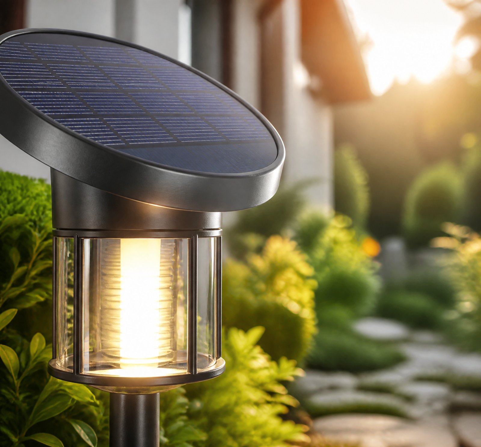
> Quick answer: Common failures of an IP65 seal in solar lamps include gasket compression set, cable gland leaks, and cracked lenses. These are driven by material incompatibility, thermal cycling, and mechanical stress. Early signs can be detected through visual inspection for cracks, discoloration, or internal moisture.
Understanding the common failure points of IP65 seals in solar lamps is crucial for ensuring their longevity and performance. In this article, we will explore the primary causes of these failures—gasket compression set, cable gland leaks, and cracked lenses—and provide actionable tips on how to inspect for early signs.
Common Failure Points: A Detailed Look
Gasket Compression Set
Gasket compression set is a significant issue in long-term sealing applications. This occurs when elastomeric seals undergo permanent deformation under sustained load [1][7]. While the sources do not explicitly mention „compression set,” they describe how material fatigue and stress can lead to cracking at interfaces, compromising sealing integrity [4][9].
Improper installation or lack of lubrication during assembly may accelerate gasket deformation. For instance, grease is used in some designs to prevent optic movement-induced pinching or pulling of the silicone gasket [4][9]. This highlights that proper assembly and maintenance are critical for preventing premature failure.
Cable Gland Leaks
Cable gland leaks can occur if these entry points are not properly sealed with compatible gaskets or tightened correctly. The patent US8585245B2 describes a sealing system using multiple o-rings and gaskets at critical interfaces, including those for screws and optic connections [4][9]. If the cable glands are loose or degraded, moisture can enter through the conduit, especially under wind-driven rain [3].
Cracked Lenses
Cracked lenses in solar lamps can result from material thinning, edge defects, and thermal stress. While explicitly mentioned in the context of solar modules, similar principles apply to solar lamps using polycarbonate or tempered glass lenses [11][24]. Delamination and poor encapsulant coverage may create stress concentration points, leading to cracking even under normal temperature changes.
Early Signs of Seal Degradation
Visual Inspection Tips
Early signs of seal degradation can be detected through careful visual inspection. Look for visible cracks in seals or gaskets at material interfaces [1][7]. Discoloration in the gasket material may indicate UV degradation or material breakdown [19]. Additionally, the presence of moisture inside the enclosure—visible as condensation or water droplets—is a clear sign of failed seals [3].
Checking for Corrosion and Loose Connections
Inspect for loose or corroded connections, which can indicate water ingress. The sources recommend checking metal components for signs of corrosion, as this can compromise structural and sealing integrity [10]. Ensuring that all fittings are tight and free from moisture is crucial for maintaining IP65 standards.
Preventative Measures and Best Practices
Material Compatibility and Design
The patent US8585245B2 emphasizes the importance of designing sealing systems to accommodate material expansion and contraction. Static, rigid seals are inherently less reliable [1][7]. Multi-layered or dynamic sealing systems may be more durable in environments with wide temperature swings.
Environmental Factors
While temperature and moisture are primary contributors to failure, other environmental factors like wind and salt air can also play a role. Salt air may accelerate corrosion of metal components, affecting the seal’s integrity [3][10]. High temperatures can soften gaskets and reduce their sealing effectiveness [24].
Key Takeaways
- Gasket compression set, cable gland leaks, and cracked lenses are common failure points in IP65 seals.
- Early signs include visible cracks, discoloration, moisture ingress, and loose fittings.
- Proper design accommodating material expansion and contraction is crucial for long-term reliability.
Frequently Asked Questions
[
{„q”: „What causes gasket compression set?”, „a”: „Gasket compression set occurs when elastomeric seals undergo permanent deformation under sustained load. This can be exacerbated by improper installation or lack of lubrication during assembly [4][9].”},
{„q”: „How do I check for cable gland leaks?”, „a”: „Cable gland leaks can be identified through visual inspection for loose fittings, moisture ingress, and corrosion on metal components [3]. Proper tightening and use of compatible gaskets are crucial [4][9].”},
{„q”: „What are the signs of a cracked lens?”, „a”: „Cracked lenses typically show visible cracks or stress lines. Poor encapsulant coverage or material thinning can lead to cracking, especially under thermal stress [11][24].” }
]
References
- [1] US8585245B2_-_Systems_and_methods_for_sealing_-_Google_Patents__154e7e2e — patent
source passage
may cause problems and even malfunctions of lighting units which may include electronic and/or electrical components. Short circuit contacts may be caused by water or humidity which may destroy the electronic components such as switches or processors, thus decreasing the life span of the lighting fixtures and increasing the maintenance cost. Shielding the lighting units from these natural elements may become even more challenging as the rates of extension and contraction of different materials used for building the lighting fixtures may vary. This variation in extension and contraction rates between different materials may cause seals to crack along the interfaces of these materials. The cracks may provide openings for leakages, which may be even exacerbated by future contractions and expansions of materials as some parts of lighting units expand much more than other parts. – the present disclosure addresses these issues by providing a reliable and comprehensive enclosure system that seals a lighting fixture from outside elements. – the systems, apparatuses and techniques of the present disclosure provide a lasting seal for the lighting fixture regardless of the rates of expansion and contraction different materials may experience. – the systems, apparatuses and techniques described herein also allow for a water-tight seal regardless of sizes and lengths of enclosure components. – the solution presented may utilize one or more silicone gaskets in combination with one or more
- [3] How_Does_Weather_Affect_PV_System_Degradation_and_Performance__c64c4d74 — authority
source passage
stresses. Researchers also warned that recent design trends like thinner cells, thinner front glass, and bigger modules may increase the likelihood of system vulnerability if not tested and designed correctly. Reviewing maintenance and operation records and monitoring PV assets would be a more proactive approach to detecting degradation among new module designs. NREL assembled a set of pre-storm checklists intended for utilities and independent power producers who own or operate solar PV installations. Depending on the system, electrical-specific steps generally require checking connectors, wiring, supports, and waterproofing. For example, in utility-scale ground-mounted systems, electrical staff should examine cable connections for corrosion, ensure the J-box is securely attached to the module, and check the grounding system for the tightness of connections and electrical continuity, among other considerations. It also suggests replacing parts like DC system wiring, cable materials, and enclosures. Waterproofing involves checking gaskets, conduit fittings, and seals to prevent wind-swept rain, then tightening or applying outdoor-rated sealant if necessary. Installing a weep hole in the bottom of the enclosure can also prevent moisture from escaping.
- [4] US8585245B2_-_Systems_and_methods_for_sealing_-_Google_Patents__154e7e2e — patent
source passage
the optic is aggressive in moving, the grease may ensure that the optic 140 will not pinch or pull the silicone gasket 120 during this movement. In a further example, assembly of the enclosure of the lighting fixture may start with adding some grease to the inside of the optic cavity of the silicone gasket. Once the silicone gasket has been pre-greased, it may be slid onto the optic overhanging the extrusion and the 4 o-rings also overhanging the extrusion may be slid through the gasket. The o-rings may be cut flush with the outward face of the gasket which may be compressed against the end cap. The end cap then may be slid over the top of the gasket and compressed by evenly tightening the 5 screws which are inserted through the end cap, through the gasket, and into the threaded holes in the extrusion. When the screws compress the gasket, the openings in the gasket may begin to squeeze. The holes for the screws may be compressed around the screw and seal it. The outside of the interface between the end cap and the extrusion may also be sealed by this compression of the gasket against the flat of the extrusion. The gasket over the top of the optic may also seal and the lip on the end cap may be keep even downward pressure against the optic. In some embodiments, all four o-rings may be compressed around and sealed while the ones on the top are also tightly squeezed against the side of the optic keeping it sealed. The label may be added and the end cap assembly may then be compl
- [7] US8585245B2_-_Systems_and_methods_for_sealing_-_Google_Patents__154e7e2e — patent
source passage
systems, such as the lighting systems may be used in a variety of applications and deployed in many different settings and environments. Lighting fixtures may be used in environments that are prone to exposure to natural elements, such as rain, snow, heat, cold, humidity, water or wind. These and other natural elements may cause problems and even malfunctions of lighting units which may include electronic and/or electrical components. Short circuit contacts may be caused by water or humidity which may destroy the electronic components such as switches or processors, thus decreasing the life span of the lighting fixtures and increasing the maintenance cost. Shielding the lighting units from these natural elements may become even more challenging as the rates of extension and contraction of different materials used for building the lighting fixtures may vary. This variation in extension and contraction rates between different materials may cause seals to crack along the interfaces of these materials. The cracks may provide openings for leakages, which may be even exacerbated by future contractions and expansions of materials as some parts of lighting units expand much more than other parts. The present disclosure addresses these issues by providing a reliable and comprehensive enclosure system that seals a lighting fixture from outside elements. The systems, apparatuses and techniques of the present disclosure provide a lasting seal for the lighting fixture regardless of the ra
- [9] US8585245B2_-_Systems_and_methods_for_sealing_-_Google_Patents__154e7e2e — patent
source passage
in moving, the grease may ensure that the optic 140 will not pinch or pull the silicone gasket 120 during this movement. – assembly of the enclosure of the lighting fixture may start with adding some grease to the inside of the optic cavity of the silicone gasket. – the silicone gasket Once the silicone gasket has been pre-greased, it may be slid onto the optic overhanging the extrusion and the 4 o-rings also overhanging the extrusion may be slid through the gasket. – the o-rings may be cut flush with the outward face of the gasket which may be compressed against the end cap. – the end cap then may be slid over the top of the gasket and compressed by evenly tightening the 5 screws which are inserted through the end cap, through the gasket, and into the threaded holes in the extrusion. When the screws compress the gasket, the openings in the gasket may begin to squeeze. – the holes for the screws may be compressed around the screw and seal it. – the outside of the interface between the end cap and the extrusion may also be sealed by this compression of the gasket against the flat of the extrusion. – the gasket over the top of the optic may also seal and the lip on the end cap may be keep even downward pressure against the optic. – all four o-rings may be compressed around and sealed while the ones on the top are also tightly squeezed against the side of the optic keeping it sealed. – the label may be added and the end cap assembly may then be complete. – the enclosure may be t
- [10] Solar_Street_Light_From_Germany__Why_Solar_Street_Lighting_Fails_in_Storms_Structural_Integrity_for_EPC_Projects__yvEyflD92L4 — youtube
source passage
# Why Solar Street Lighting Fails in Storms? (Structural Integrity for EPC Projects) Source: YouTube — Solar Street Light From Germany URL: https://www.youtube.com/watch?v=yvEyflD92L4 Video ID: yvEyflD92L4 Transcript: generated The long-term durability of a solar street lighting project doesn't depend only on the battery. It also depends on how strong and stable the structure is. Often, lights collapse during powerful storms or the body corrodes within just a few months due to salty air. This puts your entire investment at serious risk. Why do such mechanical failures occur? In today's technical discussion, we'll explore the real secrets behind the durability of solar street lighting systems. In coastal or industrial areas, salt in the air causes iron or regular steel bodies to oxidize quickly and develop rust. Once holes form in the structure, rainwater can directly reach the battery and circuitry, rendering the entire system unusable. On the other hand, low-quality plastic bodies tend to crack under excessive sunlight. Once this kind of damage begins, it becomes nearly impossible to repair and significantly increases the overall project cost. When lights are installed on tall poles, wind pressure or wind load increases significantly. If the bracket or overall mechanical design isn't properly engineered, even winds of 100 km/h can cause the light to detach from the pole and fall. This is not only a financial loss, but also a serious safety hazard. We need to understand why m
- [11] Module_reliability_scorecard_reveals_widespread_quality_risk__c7271aa4 — magazine
source passage
up from just 7% in both the 2023 and 2024 scorecards, and that the load testing conducted as part of the Reliability Scorecard goes up to 1800 pascals of pressure, rather than the 2400 specified in IEC testing standards. “These are the types of conditions that with wind loads and snow loads can occur in the field. And I don’t know what other industry would accept a 20% failure rate.” These increased breakage rates have been seen in the field already in recent years, and the move to larger module formats, made with thinner glass, is one part of the problem. But it also comes down to cost cutting efforts as manufacturers look to cut back on material consumption in times of low prices for PV components. “Probably the biggest concerning aspect of this report is that module breakage has really increased, which has a direct correlation to cost cutting,” said Erion-Lorico. In some cases, lack of encapsulant material at the edge of a module was shown to be enough to cause glass breakage, with solder points on the glass creating stress concentration points. With these, even day-to-day temperature changes could be enough to cause glass to break at the edges. “There’s a range of causes, whether that’s glass strengthening issues, flaws within the glass, weaker frame designs, edge pinch on the laminates, poor frame sealant approaches, and more aggressive mounting systems,” Erion-Lorico added. The tests also showed an increase in overall failure rate, with products from 83% of manufacturer
- [19] EP2059899A2_-_Genius_adaptive_design_-_Google_Patents__55cef7e3 — patent
source passage
such points have deteriorated (liquid has seeped into their crevices / developed cracks). Shows a weakness in the PVC structure, though no leakage outside of the pvc/container may have occurred. Helps if the PVC is clear / opaque to see any nr (color change where the deterioration is seen). -plastic bags: can show weaker welding points -part of material used in the welding process can be treated like a separate layer (as described in this n's description). Example: it is (a portion of) this welded material that causes the nr (upon the welded material's exposure/deterioration). -mf: prior to welding, the points to be welded have indicators applied onto them. These indicators may withstand temperature needed for welding. Value: catch deterioration/poor manufacturing of PVC n, prior to (further) usage. If only an outer / * inner layer (main material) has Deteriorated, then e ither that Deteriorated layer / or the underlying material/layer can induce nr (emit color dye) designating side/location of occurrence. Example: multi-layer glove, outer layer wears out (outer layer emits mild nr ('notifier alerts user) until its all worn off/Deteriorated); subsequently, when next inner layer is exposed, latter emits red dye, functioning like animal's skin. U is given warning prior to leakage / complete deterioration. Values: when wearing gloves, reduces chance of contracting unwanted elements which are carcinogenic, otherwise unhealthy, avoids hot liquid from work tank filling into glove,
- [24] Shining_a_light_on_extreme_weather_events_and_the_need_for__1e46177b — magazine
source passage
averages. With solar efficiency dependent on thermal design to ensure optimum performance in specific territories, existing PV assets are increasingly at risk as our climate continues to warm and extreme heatwaves become more prevalent and unpredictable. With PV module designs tailored to suit average regional temperatures, assets are woefully unprepared for ongoing extreme heat, which risks damaging electrical equipment bereft of adequate ventilation. Depending on the design and the region, heatwaves can cause permanent damage to PV modules and risk downtime as a result of repairs or retrofitting. While expensive, it may be necessary for pre-existing solar farms in traditionally cooler climes to consider re-assessing their ventilation to reduce longer-term ambient temperatures within the module. This can improve transformer lifetimes and decrease the chances of a catastrophic fire. Solar fire risk Located within PV modules, electrical transformers can take only so much punishment and, with record-breaking heatwaves pushing up electricity use, transformers are at risk of rapidly ageing. With solar sites staying warmer in the evening during prolonged periods of heat, transformers do not get a chance to recover. The increase in loading on a transformer creates a higher chance of failure for the equipment, which can lead to a power outage and even a catastrophic fire, resulting in total loss of the asset. The deterioration of solar equipment as a result of extreme heat is likely
may cause problems and even malfunctions of lighting units which may include electronic and/or electrical components. Short circuit contacts may be caused by water or humidity which may destroy the electronic components such as switches or processors, thus decreasing the life span of the lighting fixtures and increasing the maintenance cost. Shielding the lighting units from these natural elements may become even more challenging as the rates of extension and contraction of different materials used for building the lighting fixtures may vary. This variation in extension and contraction rates between different materials may cause seals to crack along the interfaces of these materials. The cracks may provide openings for leakages, which may be even exacerbated by future contractions and expansions of materials as some parts of lighting units expand much more than other parts. – the present disclosure addresses these issues by providing a reliable and comprehensive enclosure system that seals a lighting fixture from outside elements. – the systems, apparatuses and techniques of the present disclosure provide a lasting seal for the lighting fixture regardless of the rates of expansion and contraction different materials may experience. – the systems, apparatuses and techniques described herein also allow for a water-tight seal regardless of sizes and lengths of enclosure components. – the solution presented may utilize one or more silicone gaskets in combination with one or more
stresses. Researchers also warned that recent design trends like thinner cells, thinner front glass, and bigger modules may increase the likelihood of system vulnerability if not tested and designed correctly. Reviewing maintenance and operation records and monitoring PV assets would be a more proactive approach to detecting degradation among new module designs. NREL assembled a set of pre-storm checklists intended for utilities and independent power producers who own or operate solar PV installations. Depending on the system, electrical-specific steps generally require checking connectors, wiring, supports, and waterproofing. For example, in utility-scale ground-mounted systems, electrical staff should examine cable connections for corrosion, ensure the J-box is securely attached to the module, and check the grounding system for the tightness of connections and electrical continuity, among other considerations. It also suggests replacing parts like DC system wiring, cable materials, and enclosures. Waterproofing involves checking gaskets, conduit fittings, and seals to prevent wind-swept rain, then tightening or applying outdoor-rated sealant if necessary. Installing a weep hole in the bottom of the enclosure can also prevent moisture from escaping.
the optic is aggressive in moving, the grease may ensure that the optic 140 will not pinch or pull the silicone gasket 120 during this movement. In a further example, assembly of the enclosure of the lighting fixture may start with adding some grease to the inside of the optic cavity of the silicone gasket. Once the silicone gasket has been pre-greased, it may be slid onto the optic overhanging the extrusion and the 4 o-rings also overhanging the extrusion may be slid through the gasket. The o-rings may be cut flush with the outward face of the gasket which may be compressed against the end cap. The end cap then may be slid over the top of the gasket and compressed by evenly tightening the 5 screws which are inserted through the end cap, through the gasket, and into the threaded holes in the extrusion. When the screws compress the gasket, the openings in the gasket may begin to squeeze. The holes for the screws may be compressed around the screw and seal it. The outside of the interface between the end cap and the extrusion may also be sealed by this compression of the gasket against the flat of the extrusion. The gasket over the top of the optic may also seal and the lip on the end cap may be keep even downward pressure against the optic. In some embodiments, all four o-rings may be compressed around and sealed while the ones on the top are also tightly squeezed against the side of the optic keeping it sealed. The label may be added and the end cap assembly may then be compl
systems, such as the lighting systems may be used in a variety of applications and deployed in many different settings and environments. Lighting fixtures may be used in environments that are prone to exposure to natural elements, such as rain, snow, heat, cold, humidity, water or wind. These and other natural elements may cause problems and even malfunctions of lighting units which may include electronic and/or electrical components. Short circuit contacts may be caused by water or humidity which may destroy the electronic components such as switches or processors, thus decreasing the life span of the lighting fixtures and increasing the maintenance cost. Shielding the lighting units from these natural elements may become even more challenging as the rates of extension and contraction of different materials used for building the lighting fixtures may vary. This variation in extension and contraction rates between different materials may cause seals to crack along the interfaces of these materials. The cracks may provide openings for leakages, which may be even exacerbated by future contractions and expansions of materials as some parts of lighting units expand much more than other parts. The present disclosure addresses these issues by providing a reliable and comprehensive enclosure system that seals a lighting fixture from outside elements. The systems, apparatuses and techniques of the present disclosure provide a lasting seal for the lighting fixture regardless of the ra
in moving, the grease may ensure that the optic 140 will not pinch or pull the silicone gasket 120 during this movement. – assembly of the enclosure of the lighting fixture may start with adding some grease to the inside of the optic cavity of the silicone gasket. – the silicone gasket Once the silicone gasket has been pre-greased, it may be slid onto the optic overhanging the extrusion and the 4 o-rings also overhanging the extrusion may be slid through the gasket. – the o-rings may be cut flush with the outward face of the gasket which may be compressed against the end cap. – the end cap then may be slid over the top of the gasket and compressed by evenly tightening the 5 screws which are inserted through the end cap, through the gasket, and into the threaded holes in the extrusion. When the screws compress the gasket, the openings in the gasket may begin to squeeze. – the holes for the screws may be compressed around the screw and seal it. – the outside of the interface between the end cap and the extrusion may also be sealed by this compression of the gasket against the flat of the extrusion. – the gasket over the top of the optic may also seal and the lip on the end cap may be keep even downward pressure against the optic. – all four o-rings may be compressed around and sealed while the ones on the top are also tightly squeezed against the side of the optic keeping it sealed. – the label may be added and the end cap assembly may then be complete. – the enclosure may be t
# Why Solar Street Lighting Fails in Storms? (Structural Integrity for EPC Projects) Source: YouTube — Solar Street Light From Germany URL: https://www.youtube.com/watch?v=yvEyflD92L4 Video ID: yvEyflD92L4 Transcript: generated The long-term durability of a solar street lighting project doesn't depend only on the battery. It also depends on how strong and stable the structure is. Often, lights collapse during powerful storms or the body corrodes within just a few months due to salty air. This puts your entire investment at serious risk. Why do such mechanical failures occur? In today's technical discussion, we'll explore the real secrets behind the durability of solar street lighting systems. In coastal or industrial areas, salt in the air causes iron or regular steel bodies to oxidize quickly and develop rust. Once holes form in the structure, rainwater can directly reach the battery and circuitry, rendering the entire system unusable. On the other hand, low-quality plastic bodies tend to crack under excessive sunlight. Once this kind of damage begins, it becomes nearly impossible to repair and significantly increases the overall project cost. When lights are installed on tall poles, wind pressure or wind load increases significantly. If the bracket or overall mechanical design isn't properly engineered, even winds of 100 km/h can cause the light to detach from the pole and fall. This is not only a financial loss, but also a serious safety hazard. We need to understand why m
up from just 7% in both the 2023 and 2024 scorecards, and that the load testing conducted as part of the Reliability Scorecard goes up to 1800 pascals of pressure, rather than the 2400 specified in IEC testing standards. “These are the types of conditions that with wind loads and snow loads can occur in the field. And I don’t know what other industry would accept a 20% failure rate.” These increased breakage rates have been seen in the field already in recent years, and the move to larger module formats, made with thinner glass, is one part of the problem. But it also comes down to cost cutting efforts as manufacturers look to cut back on material consumption in times of low prices for PV components. “Probably the biggest concerning aspect of this report is that module breakage has really increased, which has a direct correlation to cost cutting,” said Erion-Lorico. In some cases, lack of encapsulant material at the edge of a module was shown to be enough to cause glass breakage, with solder points on the glass creating stress concentration points. With these, even day-to-day temperature changes could be enough to cause glass to break at the edges. “There’s a range of causes, whether that’s glass strengthening issues, flaws within the glass, weaker frame designs, edge pinch on the laminates, poor frame sealant approaches, and more aggressive mounting systems,” Erion-Lorico added. The tests also showed an increase in overall failure rate, with products from 83% of manufacturer
such points have deteriorated (liquid has seeped into their crevices / developed cracks). Shows a weakness in the PVC structure, though no leakage outside of the pvc/container may have occurred. Helps if the PVC is clear / opaque to see any nr (color change where the deterioration is seen). -plastic bags: can show weaker welding points -part of material used in the welding process can be treated like a separate layer (as described in this n's description). Example: it is (a portion of) this welded material that causes the nr (upon the welded material's exposure/deterioration). -mf: prior to welding, the points to be welded have indicators applied onto them. These indicators may withstand temperature needed for welding. Value: catch deterioration/poor manufacturing of PVC n, prior to (further) usage. If only an outer / * inner layer (main material) has Deteriorated, then e ither that Deteriorated layer / or the underlying material/layer can induce nr (emit color dye) designating side/location of occurrence. Example: multi-layer glove, outer layer wears out (outer layer emits mild nr ('notifier alerts user) until its all worn off/Deteriorated); subsequently, when next inner layer is exposed, latter emits red dye, functioning like animal's skin. U is given warning prior to leakage / complete deterioration. Values: when wearing gloves, reduces chance of contracting unwanted elements which are carcinogenic, otherwise unhealthy, avoids hot liquid from work tank filling into glove,
averages. With solar efficiency dependent on thermal design to ensure optimum performance in specific territories, existing PV assets are increasingly at risk as our climate continues to warm and extreme heatwaves become more prevalent and unpredictable. With PV module designs tailored to suit average regional temperatures, assets are woefully unprepared for ongoing extreme heat, which risks damaging electrical equipment bereft of adequate ventilation. Depending on the design and the region, heatwaves can cause permanent damage to PV modules and risk downtime as a result of repairs or retrofitting. While expensive, it may be necessary for pre-existing solar farms in traditionally cooler climes to consider re-assessing their ventilation to reduce longer-term ambient temperatures within the module. This can improve transformer lifetimes and decrease the chances of a catastrophic fire. Solar fire risk Located within PV modules, electrical transformers can take only so much punishment and, with record-breaking heatwaves pushing up electricity use, transformers are at risk of rapidly ageing. With solar sites staying warmer in the evening during prolonged periods of heat, transformers do not get a chance to recover. The increase in loading on a transformer creates a higher chance of failure for the equipment, which can lead to a power outage and even a catastrophic fire, resulting in total loss of the asset. The deterioration of solar equipment as a result of extreme heat is likely