
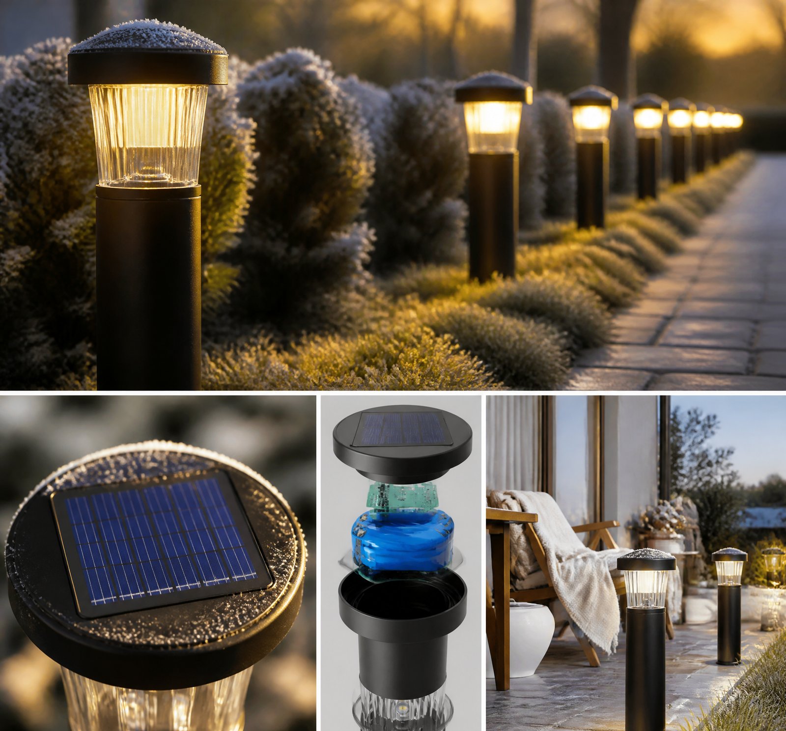
> Quick answer: To ensure a solar lamp recharges fully on short Romanian December days, the panel must deliver sufficient energy within 4–6 hours of sunlight, the battery should be sized for 14–20 days of operation at reduced load, and LED loads must be managed through dynamic dimming or PWM control [2][4][12][15][24].
In Romania’s short December days, ensuring a solar lamp recharges fully is crucial. This article delves into the key strategies for sizing panels, batteries, and LEDs to maintain consistent lighting without discharging over weeks.
Matching Panel Output to Battery Needs
To ensure full recharge on low-irradiance Romanian winter days, the panel must generate enough energy within 4–6 hours of sunlight [12][24]. For example, a 70% efficient system requires a solar panel capable of delivering at least 3.6 Wh per day to charge a 2.5 Wh battery [3].
Battery Sizing for Winter Survival
The battery must not only meet nightly demand but also withstand deep discharge cycles. Deep-cycle batteries should not be discharged beyond 50% of their capacity to preserve lifespan; thus, the usable capacity is halved [23]. For instance, a 100 Ah battery effectively provides 600 Wh of usable energy.
The most surprising and actionable insight from the corpus is that a solar lamp can survive extended winter periods—even with no sunshine—by combining dynamic dimming, motion sensing, and intelligent charge control. One system uses a motion sensor to activate full power only when movement is detected [2]. Another system maintains battery voltage at a stable level during extended overcast periods by dimming LEDs when the voltage drops [13][22].
LED Load Management
The LED load must be sized to match the battery’s usable capacity and the panel’s output. A typical setup uses 8 LEDs, each drawing 320 mA at high power (90 lumens) or 220 mA at low power (70 lumens). The system often operates with multiple power levels—low, high, and intermittent—and Pulse-Width Modulation (PWM) to vary LED intensity dynamically [16].
Dynamic Dimming
Dynamic dimming reduces the total energy draw during the night. For instance, one system programs LED intensity at 100% for the first 4 hours, 50% for the next 4 hours, and 20% for the remainder of the night [2]. This approach extends battery life through low-irradiance periods.
Intelligent Power Management Systems
Intelligent charge controllers are programmed based on night duration. Winter nights—ranging from 12–14 hours—require a more conservative power profile to ensure that the system can survive multiple overcast days [2][13].
| Component | Role |
|––––|––––––-|
| Solar Panel | Generates energy within limited sunlight. |
| Battery | Stores energy for extended use; must be sized for deep discharge cycles. |
| LEDs | Managed through dynamic dimming and PWM to reduce power draw. |
Key Takeaways
- A solar lamp can survive Romanian winter days if the panel is large enough to recharge within 4–6 hours.
- The battery should provide 14–20 days of operation at reduced load.
- Dynamic dimming, motion sensing, or PWM control manages LED loads effectively.
References
- [2] US10563827B2_-_Solar_powered_illumination_system_-_Google_Patents__f82b6692 — patent
source passage
possesses high efficiency in cloudy, rainy, snowy and dusty areas due to efficient charging of the rechargeable battery and energy conservation. The illumination system further implements a programmable charge controller or a motion sensor in areas where the daytime is too short. The illumination system increases a power back-up to 14-20 days. When the motion sensor detects an object movement from a specific distance, the illumination system starts working with 100% of power, otherwise the illumination system works at 20-40% of a rated power value based on pre-defined programming. Furthermore, the charge controllers are programmed based on duration of a night in a geographical location such as 8 hours in summer and 12-14 hours in winter. On the basis of night duration, a light intensity is programmed to be at 100% for the first 4 hours, 50% for the following 4 hours and 20% for the rest of the night until the sunrise. According to one embodiment herein, for installing the illumination system in desert or snowy areas following customizations are adopted: – – a. Increasing a tilt angle of the solar panels during installation without decrease in the solar light absorption. The solution reduces an accumulation of dust, snow and rain on the surface of the solar panel. – b. Using a self-cleansing Nano-coating on the solar panels to decrease a friction on the surface of the solar panel which also prevents the accumulation of dust, snow and rain on the surface of the solar panel. Acc
- [3] Feeding_stereoids_to_3_solar_lantern_Forum__d5420992 — authority
source passage
# EEVblog® Electronics Community Forum Source: Blog/Web URL: https://www.eevblog.com/forum/beginners/feeding-stereoids-to-3$-solar-lantern/ Author: Author Date: 2017-11-13 Typical cheap AAA NiMH cells have a capacity of roughly 700mAH, and a three cell pack will store about 2.5WH (9KJ). With a high effeciency charging circuit, total energy effiency may reach 70%. The battery will therefore require 3.6WH to fully recharge. Average Direct Normal Irradiance for India is about 4.8KWH/m2/day. Assuming 20% efficient solar cells, 1m2 of panel area in a fixed position and optimally tilted, can be expected to produce 4.8*0.2=0.96KWH per day. Therefore the minimum panel area to recharge the battery in 1 day is 3.6/960=0.00375m2 or 37.5cm2. That's slightly over 6cm x 6cm of active panel surface. There's no way that lantern has that much active panel area, (only exposed silicon surface counts, not bus strips, interconnects etc), and it is extremely unlikely its got 20% efficiency cells and unless you tilt it just right in an un-shaded location you aren't going to get that much irradiance. Take a photo of the panel with a ruler in shot for scale and we can probably calculate if the panel could provide any useful recharge capability if the charger circuit was improved, or if its essentially worthless. Fitting higher power LEDs certainly wont have helped. You should measure the current drawn by the original LED (hook it to the USB output) with the battery fully charged and time the discharg
- [4] WO2014070291A1_-_Inflatable_solar_powered_lamp_-_Google_Patents__ae93c58e — patent
source passage
when the solar panel is laid flat in direct sunlight, the rechargeable battery is completely charged in 4 to 8 hours, with sufficient charge to yield more than 6 hours of light and preferably more than 8 hours of light once fully charged. Although any number of LEDs may be used within the scope of the invention, 6 to 10 LEDs is preferable, and 8 is most preferred. The LEDs provide a 4000 mcd light source, sufficient to illuminate a 10 square foot area with usable lighting. In embodiments, multicolored LEDs may be used. Use of multicolor LEDs may be functional, such as red or yellow to indicate emergency condition, or decorative. [0013] The rechargeable battery 40 is preferably a lithium-ion polymer battery with a thin profile that can be readily incorporated onto a printed circuit board. In the most preferred embodiments, the rechargeable battery has a thickness of no more than about 5 mm, a capacity of 1000 mAh, and a nominal operating voltage of 3.7 V. wherein the planar array of LEDs consists of eight LEDs arranged in a circle and powered by the battery. In a preferred embodiment, each LED has a maximum operating current of 320 mA at 90 lumens (high power) and 220 mA at 70 lumens (low power). [0014] The printed circuit board 200 controls the powering of the LEDs by the battery 40. A user activates a power switch 204 located on the exterior of the lamp to power the LEDs. In embodiments, the circuit board controls three levels of illumination: low power, high power and inter
- [12] EP2914896B1_-_Inflatable_solar_powered_lamp_-_Google_Patents__37bca5de — patent
source passage
in FIG. 1B) adapted to recharge the rechargeable battery 40. The solar panel is exposed to the sunlight through the clear outer bottom 164 through an aperture in bottom frame 160. The printed circuit board is attached to bottom frame member 166 with double sided tape 202. A solar panel for use with the invention may be selected from those known in the art to be adapted to power a small LED array. A suitable solar panel is a polycrystalline 5V/130mA array with an open circuit voltage of 4.3 V, a short circuit current of about 3.5 A, and an optimum operating voltage of 2.6 V. Generally, when the solar panel is laid flat in direct sunlight, the rechargeable battery is completely charged in 4 to 8 hours, with sufficient charge to yield more than 6 hours of light and preferably more than 8 hours of light once fully charged. Although any number of LEDs may be used within the scope of the invention, 6 to 10 LEDs is preferable, and 8 is most preferred. The LEDs provide a 4000 mcd light source, sufficient to illuminate a 10 square foot area with usable lighting. In embodiments, multicolored LEDs may be used. Use of multicolor LEDs may be functional, such as red or yellow to indicate emergency condition, or decorative. The rechargeable battery 40 is preferably a lithium-ion polymer battery with a thin profile that can be readily incorporated onto a printed circuit board. In the most preferred embodiments, the rechargeable battery has a thickness of no more than about 5 mm, a capacity o
- [13] WO2010057138A2_-_Energy-efficient_solar-powered_outdoor_lighting__593d23e6 — patent
source passage
to or contribution of energy from the electrical grid, without any replacement of the batteries, and without any energy input into the batterys or any part of the lighting system except from the amorphous PV cell material on each pole. [0292] In Figure 50, one may see long periods of days and weeks of sky cover (measured in hours during the day, defined as "cloudy" or "overcast" as judged from the local weather report), but the system maintained minimum battery voltage above the important benchmark of approximately 1 1 volts all through the roughly two month winter period, except for the "waving tree limb" incident in December, described above. In Figures 51 A and B, which represent a different test, of a set of poles operating over about 2.5 winter months (the graph being split roughly in two), multiple poles operating independent of each other and autonomously (not tied to the grid) all performed continuously at or above 1 1 volts throughout the winter, despite long stretches of little or no sunshine per day. Even during the dark days of January, only a few of the poles came near to dropping to 1 1 volts, at which increased dimming action per the energy-savings mode E6 kept the poles operating successfully, at least at dimmed condition, during the crucual periods after dusk and before dawn, and upon motion being sensed. Up an increase in sunshine late in January, the batteries all rebounded to a range of 12 — 12.5 volts. [0294] Preferred embodiments may therefore be describ
- [15] US9194563B2_-_Inflatable_solar_powered_lamp_-_Google_Patents__d4ff4a04 — patent
source passage
optimum operating voltage of 2.6 V. Generally, when the solar panel is laid flat in direct sunlight, the rechargeable battery is completely charged in 4 to 8 hours, with sufficient charge to yield more than 6 hours of light and preferably more than 8 hours of light once fully charged. Although any number of LEDs may be used within the scope of the invention, 6 to 10 LEDs is preferable, and 8 is most preferred. The LEDs provide a 4000 mcd light source, sufficient to illuminate a 10 square foot area with usable lighting. In embodiments, multicolored LEDs may be used. Use of multicolor LEDs may be functional, such as red or yellow to indicate emergency condition, or decorative. The rechargeable battery 40 is preferably a lithium-ion polymer battery with a thin profile that can be readily incorporated onto a printed circuit board. In the most preferred embodiments, the rechargeable battery has a thickness of no more than about 5 mm, a capacity of 1000 mAh, and a nominal operating voltage of 3.7 V. wherein the planar array of LEDs consists of eight LEDs arranged in a circle and powered by the battery. In a preferred embodiment, each LED has a maximum operating current of 320 mA at 90 lumens (high power) and 220 mA at 70 lumens (low power). The printed circuit board 200 controls the powering of the LEDs by the battery 40. A user activates a power switch 204 located on the exterior of the lamp to power the LEDs. In embodiments, the circuit board controls three levels of illumination
- [16] US9920895B2_-_Street_light_-_Google_Patents__b32f25f2 — patent
source passage
below a certain threshold level, in order to prevent damage to the battery. – the charging circuit 23 is further programmed to take account of the variation in the number of daylight hours that the solar panel will receive throughout the year. For this, it is programmed to periodically: – the control circuit 24 is programmed to control the lamp brightness by varying the intensity of the LEDs 40 via Pulse-Width Modulation (PWM). – PWM Pulse-Width Modulation – Various modes of operation of the lamp can be programmed, the intensity of the brightness varying with time or, if a light sensor is provided, with the ambient light levels. – a high brightness setting is required at times of high densities of traffic or pedestrians in the vicinity of the light 1 and a low brightness setting is required at times of low densities of traffic or pedestrians. – the lamp 5 comprises an array of Light Emitting Diodes (LEDs) 40 and their respective drivers 42 . – LEDs Light Emitting Diodes – the power consumption of the LED array is rated at 11 W and the brightness is equivalent to a conventional 28 W-55 W low pressure sodium discharge lamp. – Reflectors 44 are provided in the lamp 5 behind the LEDs to direct light towards the street. – the control circuit 24 is further programmed to switch on and off certain ones of the LEDs to vary the pattern of illumination or as another way to alter the lamp brightness. – the battery 20 typically consists of four 12V, 20 AH lead acid batteries stacked to fo
- [22] US20120020060A1_-_Energy-efficient_solar-powered_-_Google_Patents__619c8cff — patent
source passage
accomplished, without any tie to or contribution of energy from the electrical grid, without any replacement of the batteries, and without any energy input into the batterys or any part of the lighting system except from the amorphous PV cell material on each pole. – In FIG. 50 , one may see long periods of days and weeks of sky cover (measured in hours during the day, defined as “cloudy” or “overcast” as judged from the local weather report), but the system maintained minimum battery voltage above the important benchmark of approximately 11 volts all through the roughly two month winter period, except for the “waving tree limb” incident in December, described above. InFIGS. 51A and B, which represent a different test, of a set of poles operating over about 2.5 winter months (the graph being split roughly in two), multiple poles operating independent of each other and autonomously (not tied to the grid) all performed continuously at or above 11 volts throughout the winter, despite long stretches of little or no sunshine per day. Even during the dark days of January, only a few of the poles came near to dropping to 11 volts, at which increased dimming action per the energy-savings mode E6 kept the poles operating successfully, at least at dimmed condition, during the crucual periods after dusk and before dawn, and upon motion being sensed. Up an increase in sunshine late in January, the batteries all rebounded to a range of 12-12.5 volts. – Preferred embodiments may therefore
- [23] WikipediaReference_deskArchivesScience2010_-_Wikipedia__66e32724 — wikipedia
source passage
# Wikipedia:Reference desk/Archives/Science/2010 November 11 – Wikipedia Source: Blog/Web URL: https://en.wikipedia.org/wiki/Wikipedia:Reference_desk/Archives/Science/2010_November_11 Author: Date: 2010-11-11 —Preceding unsigned comment added by Kright19 (talk • contribs) 03:37, 11 November 2010 (UTC) – Ariel. (talk) 03:53, 11 November 2010 (UTC) – One more formula you might find helpful in planning is this. Battery capacities are often expressed in amp-hours rather than watt-hours; to convert amp-hour capacities to watt-hours, multiply the amp-hour rating by the voltage of the battery (usually 12 volts). For example, a 100 amp-hour (A·hr) 12 volt battery has a capacity of 1200 watt-hours. Worth remembering, too, is that you should aim to exhaust no more than about 50% of the capacity of a deep-cycle battery before recharging; repeated deep or full discharges will shorten the battery life significantly. (So that 100 amp-hour battery should only be thought of as good for 600 watt-hours storage.) Battery performance may also be poorer under cold-weather conditions, and deeply discharged batteries are prone to freezing damage. On the bright side, if your battery and inverter are inside the coop with the chickens (but protected from pecking!) then all of the charging, discharging, and inverter inefficiencies that would show up as 'waste' heat will at least be going into keeping the coop warm. – To sum up — for winter heating use, you're probably going to need significantly more c
- [24] US9638399B2_-_Inflatable_solar_powered_lamp_-_Google_Patents__71cbc60b — patent
source passage
the battery. – each LED has a maximum operating current of 320 mA at 90 lumens (high power) and 220 mA at 70 lumens (low power). – the printed circuit board 200 controls the powering of the LEDs by the battery 40 . – a user activates a power switch 204 located on the exterior of the lamp to power the LEDs. – the circuit board controls three levels of illumination: low power, high power and intermittent. The levels can be obtained by pressing the same power switch used to turn the device off and on. For example, the switch may be pressed once for low power, twice for high power, three times for intermittent, and four times to turn the device off. Sourcing a suitable such microchip for this purpose may be left to the skill of the ordinarily skilled artisan. – the housing is collapsible and is preferably inflatable through a valve 123 through the top end wall 13 . Apertures are provided in the top reflector and inner top into the interior of the housing so that the housing can be inflated, resulting in a low-cost, lightweight and durable lighting solution for those in need. Landscapes – Engineering & Computer Science (AREA) – General Engineering & Computer Science (AREA) – Life Sciences & Earth Sciences (AREA) – Sustainable Development (AREA) – Non-Portable Lighting Devices Or Systems Thereof (AREA) – Arrangement Of Elements, Cooling, Sealing, Or The Like Of Lighting Devices (AREA) – Fastening Of Light Sources Or Lamp Holders (AREA) Abstract A solar powered lamp is provided with
possesses high efficiency in cloudy, rainy, snowy and dusty areas due to efficient charging of the rechargeable battery and energy conservation. The illumination system further implements a programmable charge controller or a motion sensor in areas where the daytime is too short. The illumination system increases a power back-up to 14-20 days. When the motion sensor detects an object movement from a specific distance, the illumination system starts working with 100% of power, otherwise the illumination system works at 20-40% of a rated power value based on pre-defined programming. Furthermore, the charge controllers are programmed based on duration of a night in a geographical location such as 8 hours in summer and 12-14 hours in winter. On the basis of night duration, a light intensity is programmed to be at 100% for the first 4 hours, 50% for the following 4 hours and 20% for the rest of the night until the sunrise. According to one embodiment herein, for installing the illumination system in desert or snowy areas following customizations are adopted: – – a. Increasing a tilt angle of the solar panels during installation without decrease in the solar light absorption. The solution reduces an accumulation of dust, snow and rain on the surface of the solar panel. – b. Using a self-cleansing Nano-coating on the solar panels to decrease a friction on the surface of the solar panel which also prevents the accumulation of dust, snow and rain on the surface of the solar panel. Acc
# EEVblog® Electronics Community Forum Source: Blog/Web URL: https://www.eevblog.com/forum/beginners/feeding-stereoids-to-3$-solar-lantern/ Author: Author Date: 2017-11-13 Typical cheap AAA NiMH cells have a capacity of roughly 700mAH, and a three cell pack will store about 2.5WH (9KJ). With a high effeciency charging circuit, total energy effiency may reach 70%. The battery will therefore require 3.6WH to fully recharge. Average Direct Normal Irradiance for India is about 4.8KWH/m2/day. Assuming 20% efficient solar cells, 1m2 of panel area in a fixed position and optimally tilted, can be expected to produce 4.8*0.2=0.96KWH per day. Therefore the minimum panel area to recharge the battery in 1 day is 3.6/960=0.00375m2 or 37.5cm2. That's slightly over 6cm x 6cm of active panel surface. There's no way that lantern has that much active panel area, (only exposed silicon surface counts, not bus strips, interconnects etc), and it is extremely unlikely its got 20% efficiency cells and unless you tilt it just right in an un-shaded location you aren't going to get that much irradiance. Take a photo of the panel with a ruler in shot for scale and we can probably calculate if the panel could provide any useful recharge capability if the charger circuit was improved, or if its essentially worthless. Fitting higher power LEDs certainly wont have helped. You should measure the current drawn by the original LED (hook it to the USB output) with the battery fully charged and time the discharg
when the solar panel is laid flat in direct sunlight, the rechargeable battery is completely charged in 4 to 8 hours, with sufficient charge to yield more than 6 hours of light and preferably more than 8 hours of light once fully charged. Although any number of LEDs may be used within the scope of the invention, 6 to 10 LEDs is preferable, and 8 is most preferred. The LEDs provide a 4000 mcd light source, sufficient to illuminate a 10 square foot area with usable lighting. In embodiments, multicolored LEDs may be used. Use of multicolor LEDs may be functional, such as red or yellow to indicate emergency condition, or decorative. [0013] The rechargeable battery 40 is preferably a lithium-ion polymer battery with a thin profile that can be readily incorporated onto a printed circuit board. In the most preferred embodiments, the rechargeable battery has a thickness of no more than about 5 mm, a capacity of 1000 mAh, and a nominal operating voltage of 3.7 V. wherein the planar array of LEDs consists of eight LEDs arranged in a circle and powered by the battery. In a preferred embodiment, each LED has a maximum operating current of 320 mA at 90 lumens (high power) and 220 mA at 70 lumens (low power). [0014] The printed circuit board 200 controls the powering of the LEDs by the battery 40. A user activates a power switch 204 located on the exterior of the lamp to power the LEDs. In embodiments, the circuit board controls three levels of illumination: low power, high power and inter
in FIG. 1B) adapted to recharge the rechargeable battery 40. The solar panel is exposed to the sunlight through the clear outer bottom 164 through an aperture in bottom frame 160. The printed circuit board is attached to bottom frame member 166 with double sided tape 202. A solar panel for use with the invention may be selected from those known in the art to be adapted to power a small LED array. A suitable solar panel is a polycrystalline 5V/130mA array with an open circuit voltage of 4.3 V, a short circuit current of about 3.5 A, and an optimum operating voltage of 2.6 V. Generally, when the solar panel is laid flat in direct sunlight, the rechargeable battery is completely charged in 4 to 8 hours, with sufficient charge to yield more than 6 hours of light and preferably more than 8 hours of light once fully charged. Although any number of LEDs may be used within the scope of the invention, 6 to 10 LEDs is preferable, and 8 is most preferred. The LEDs provide a 4000 mcd light source, sufficient to illuminate a 10 square foot area with usable lighting. In embodiments, multicolored LEDs may be used. Use of multicolor LEDs may be functional, such as red or yellow to indicate emergency condition, or decorative. The rechargeable battery 40 is preferably a lithium-ion polymer battery with a thin profile that can be readily incorporated onto a printed circuit board. In the most preferred embodiments, the rechargeable battery has a thickness of no more than about 5 mm, a capacity o
to or contribution of energy from the electrical grid, without any replacement of the batteries, and without any energy input into the batterys or any part of the lighting system except from the amorphous PV cell material on each pole. [0292] In Figure 50, one may see long periods of days and weeks of sky cover (measured in hours during the day, defined as "cloudy" or "overcast" as judged from the local weather report), but the system maintained minimum battery voltage above the important benchmark of approximately 1 1 volts all through the roughly two month winter period, except for the "waving tree limb" incident in December, described above. In Figures 51 A and B, which represent a different test, of a set of poles operating over about 2.5 winter months (the graph being split roughly in two), multiple poles operating independent of each other and autonomously (not tied to the grid) all performed continuously at or above 1 1 volts throughout the winter, despite long stretches of little or no sunshine per day. Even during the dark days of January, only a few of the poles came near to dropping to 1 1 volts, at which increased dimming action per the energy-savings mode E6 kept the poles operating successfully, at least at dimmed condition, during the crucual periods after dusk and before dawn, and upon motion being sensed. Up an increase in sunshine late in January, the batteries all rebounded to a range of 12 — 12.5 volts. [0294] Preferred embodiments may therefore be describ
optimum operating voltage of 2.6 V. Generally, when the solar panel is laid flat in direct sunlight, the rechargeable battery is completely charged in 4 to 8 hours, with sufficient charge to yield more than 6 hours of light and preferably more than 8 hours of light once fully charged. Although any number of LEDs may be used within the scope of the invention, 6 to 10 LEDs is preferable, and 8 is most preferred. The LEDs provide a 4000 mcd light source, sufficient to illuminate a 10 square foot area with usable lighting. In embodiments, multicolored LEDs may be used. Use of multicolor LEDs may be functional, such as red or yellow to indicate emergency condition, or decorative. The rechargeable battery 40 is preferably a lithium-ion polymer battery with a thin profile that can be readily incorporated onto a printed circuit board. In the most preferred embodiments, the rechargeable battery has a thickness of no more than about 5 mm, a capacity of 1000 mAh, and a nominal operating voltage of 3.7 V. wherein the planar array of LEDs consists of eight LEDs arranged in a circle and powered by the battery. In a preferred embodiment, each LED has a maximum operating current of 320 mA at 90 lumens (high power) and 220 mA at 70 lumens (low power). The printed circuit board 200 controls the powering of the LEDs by the battery 40. A user activates a power switch 204 located on the exterior of the lamp to power the LEDs. In embodiments, the circuit board controls three levels of illumination
below a certain threshold level, in order to prevent damage to the battery. – the charging circuit 23 is further programmed to take account of the variation in the number of daylight hours that the solar panel will receive throughout the year. For this, it is programmed to periodically: – the control circuit 24 is programmed to control the lamp brightness by varying the intensity of the LEDs 40 via Pulse-Width Modulation (PWM). – PWM Pulse-Width Modulation – Various modes of operation of the lamp can be programmed, the intensity of the brightness varying with time or, if a light sensor is provided, with the ambient light levels. – a high brightness setting is required at times of high densities of traffic or pedestrians in the vicinity of the light 1 and a low brightness setting is required at times of low densities of traffic or pedestrians. – the lamp 5 comprises an array of Light Emitting Diodes (LEDs) 40 and their respective drivers 42 . – LEDs Light Emitting Diodes – the power consumption of the LED array is rated at 11 W and the brightness is equivalent to a conventional 28 W-55 W low pressure sodium discharge lamp. – Reflectors 44 are provided in the lamp 5 behind the LEDs to direct light towards the street. – the control circuit 24 is further programmed to switch on and off certain ones of the LEDs to vary the pattern of illumination or as another way to alter the lamp brightness. – the battery 20 typically consists of four 12V, 20 AH lead acid batteries stacked to fo
accomplished, without any tie to or contribution of energy from the electrical grid, without any replacement of the batteries, and without any energy input into the batterys or any part of the lighting system except from the amorphous PV cell material on each pole. – In FIG. 50 , one may see long periods of days and weeks of sky cover (measured in hours during the day, defined as “cloudy” or “overcast” as judged from the local weather report), but the system maintained minimum battery voltage above the important benchmark of approximately 11 volts all through the roughly two month winter period, except for the “waving tree limb” incident in December, described above. InFIGS. 51A and B, which represent a different test, of a set of poles operating over about 2.5 winter months (the graph being split roughly in two), multiple poles operating independent of each other and autonomously (not tied to the grid) all performed continuously at or above 11 volts throughout the winter, despite long stretches of little or no sunshine per day. Even during the dark days of January, only a few of the poles came near to dropping to 11 volts, at which increased dimming action per the energy-savings mode E6 kept the poles operating successfully, at least at dimmed condition, during the crucual periods after dusk and before dawn, and upon motion being sensed. Up an increase in sunshine late in January, the batteries all rebounded to a range of 12-12.5 volts. – Preferred embodiments may therefore
# Wikipedia:Reference desk/Archives/Science/2010 November 11 – Wikipedia Source: Blog/Web URL: https://en.wikipedia.org/wiki/Wikipedia:Reference_desk/Archives/Science/2010_November_11 Author: Date: 2010-11-11 —Preceding unsigned comment added by Kright19 (talk • contribs) 03:37, 11 November 2010 (UTC) – Ariel. (talk) 03:53, 11 November 2010 (UTC) – One more formula you might find helpful in planning is this. Battery capacities are often expressed in amp-hours rather than watt-hours; to convert amp-hour capacities to watt-hours, multiply the amp-hour rating by the voltage of the battery (usually 12 volts). For example, a 100 amp-hour (A·hr) 12 volt battery has a capacity of 1200 watt-hours. Worth remembering, too, is that you should aim to exhaust no more than about 50% of the capacity of a deep-cycle battery before recharging; repeated deep or full discharges will shorten the battery life significantly. (So that 100 amp-hour battery should only be thought of as good for 600 watt-hours storage.) Battery performance may also be poorer under cold-weather conditions, and deeply discharged batteries are prone to freezing damage. On the bright side, if your battery and inverter are inside the coop with the chickens (but protected from pecking!) then all of the charging, discharging, and inverter inefficiencies that would show up as 'waste' heat will at least be going into keeping the coop warm. – To sum up — for winter heating use, you're probably going to need significantly more c
the battery. – each LED has a maximum operating current of 320 mA at 90 lumens (high power) and 220 mA at 70 lumens (low power). – the printed circuit board 200 controls the powering of the LEDs by the battery 40 . – a user activates a power switch 204 located on the exterior of the lamp to power the LEDs. – the circuit board controls three levels of illumination: low power, high power and intermittent. The levels can be obtained by pressing the same power switch used to turn the device off and on. For example, the switch may be pressed once for low power, twice for high power, three times for intermittent, and four times to turn the device off. Sourcing a suitable such microchip for this purpose may be left to the skill of the ordinarily skilled artisan. – the housing is collapsible and is preferably inflatable through a valve 123 through the top end wall 13 . Apertures are provided in the top reflector and inner top into the interior of the housing so that the housing can be inflated, resulting in a low-cost, lightweight and durable lighting solution for those in need. Landscapes – Engineering & Computer Science (AREA) – General Engineering & Computer Science (AREA) – Life Sciences & Earth Sciences (AREA) – Sustainable Development (AREA) – Non-Portable Lighting Devices Or Systems Thereof (AREA) – Arrangement Of Elements, Cooling, Sealing, Or The Like Of Lighting Devices (AREA) – Fastening Of Light Sources Or Lamp Holders (AREA) Abstract A solar powered lamp is provided with