
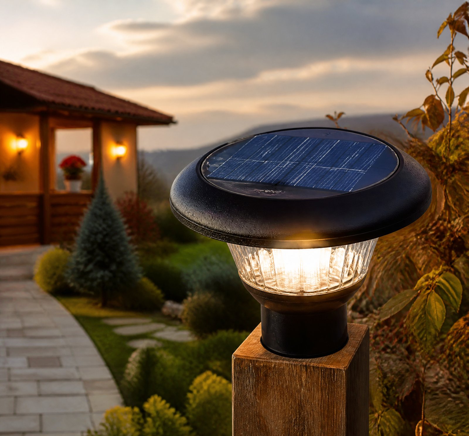
> Quick answer: In a solar lamp system, the photovoltaic panel converts sunlight into electricity [2][3], which is regulated by a charge controller for optimal battery charging [5]. The LiFePO4 battery stores energy for nighttime use [12], and LEDs provide light output controlled by motion detection from a PIR sensor [7].
The solar lamp system, consisting of photovoltaic panels, LiFePO4 batteries, charge controllers, LEDs, and PIR sensors, functions as an integrated, self-sustaining network designed to harvest, store, regulate, and deliver energy efficiently. Each component plays a crucial role in ensuring reliable lighting under various conditions.
How the Photovoltaic Panel Converts Sunlight into Energy
The photovoltaic panel is the primary source of energy for the solar lamp system [2][3]. It converts sunlight directly into electrical power during daylight hours. This generated electricity is then directed to the charge controller, which manages and regulates the energy flow to ensure optimal charging conditions for the battery.
Role of the Charge Controller in Energy Management
The charge controller plays a critical role by managing the charging process from the photovoltaic panel to the LiFePO4 battery [2][5]. It ensures that the current and voltage supplied to the battery are regulated, preventing overcharging and extending the battery’s lifespan [1][5][10][12][13].
Preventing Battery Degradation
The controller also limits maximum voltage to avoid battery degradation [12], providing real-time monitoring of battery health by assessing its voltage and temperature. This continuous monitoring allows for adaptive adjustments in charging and discharging rates, ensuring the system remains stable even during prolonged periods of poor weather conditions.
LiFePO4 Battery for Energy Storage
The rechargeable LiFePO4 battery stores electrical energy generated by the solar panel [2][5][12], which is used to power the LED lights during nighttime or low-light conditions. The battery typically resides in a protective enclosure, such as a waterproof box at the base of the pole [1][5][10].
Battery Longevity and Thermal Management
The controller continuously monitors the battery’s health to adjust charging rates, reducing stress from excessive cycles and extending its lifespan [5][10][12][13]. Advanced systems may include temperature monitoring and cooling mechanisms to maintain optimal performance over extended periods.
LED Lighting System: Efficiency and Distribution
LEDs are the primary lighting components in solar lamps. They convert stored electrical energy into visible light, providing illumination when needed [2][3]. The LEDs are often driven by a dedicated circuit that ensures consistent current delivery and prevents damage from overcurrent [2][3].
Advanced Light Distribution Techniques
Some systems use arrays or optical components like Fresnel lenses to enhance light distribution and reduce hotspots, improving both efficiency and safety [20]. This setup allows for better illumination coverage and reduces energy waste.
Motion Detection: The Role of the PIR Sensor
The passive infrared (PIR) sensor is an essential component that detects human presence to trigger lighting behavior based on occupancy [7][15][18][23]. When motion is detected, it signals the controller to increase energy delivery to the LEDs for a predetermined period before dimming back down.
Photocell Integration
The PIR sensor works in conjunction with a photocell that detects ambient light levels to determine when to turn on or off based on dawn and dusk cycles [7][18][23]. The controller uses input from both sensors to manage the timing and intensity of illumination, enabling various modes such as full brightness at dusk followed by dimming.
Central Control: System Intelligence
The system’s intelligence is centralized in a control board or software that coordinates all components [5][7][10][12][13]. This controller executes algorithms based on battery state, environmental conditions, and user-defined settings to determine energy delivery and lighting behavior [7][15][19].
Advanced Features and Customization
In more advanced systems, the controller supports wireless communication and remote control, enabling users to adjust brightness, color, or timing via a software interface [4]. Some configurations also include data logging for solar collection, charge characteristics, and environmental data to optimize performance over time.
Comparative Analysis of Different Components
| Component | Function |
|–––––––|–––––––––––––|
| Photovoltaic Panel | Converts sunlight into electricity |
| Charge Controller | Regulates charging and discharging |
| LiFePO4 Battery | Stores electrical energy |
| LEDs | Provides light output |
| PIR Sensor | Triggers lighting based on motion |
Key Takeaways
- The photovoltaic panel converts sunlight into electricity, which is then managed by the charge controller for optimal battery charging.
- LiFePO4 batteries store energy efficiently and are monitored to extend their lifespan.
- LEDs convert stored electrical energy into light, with advanced systems using arrays or optical components for better distribution.
- PIR sensors detect motion to trigger lighting, working alongside photocells for ambient light detection.
Frequently Asked Questions
[
{„q”: „How does the charge controller prevent overcharging?”, „a”: „The charge controller regulates current and voltage supplied to the battery, ensuring optimal charging conditions [5][10][12].”},
{„q”: „What role do LiFePO4 batteries play in solar lamps?”, „a”: „LiFePO4 batteries store electrical energy generated by photovoltaic panels for use during low-light or nighttime conditions [2][5][12].”},
{„q”: „How do PIR sensors work with LEDs?”, „a”: „PIR sensors detect motion and signal the controller to increase LED brightness, then dim back down after a set period [7][18][23].”}
]
References
- [1] US10563827B2_-_Solar_powered_illumination_system_-_Google_Patents__f82b6692 — patent
source passage
decrease in a number of charging/discharging cycles of the rechargeable battery, which in turn results in longer battery and charge controller lifetime. – the illumination system further has reduced maintenance cost primarily due to the longer lifetime. Landscapes – Engineering & Computer Science (AREA) – General Engineering & Computer Science (AREA) – Life Sciences & Earth Sciences (AREA) – Sustainable Development (AREA) – Power Engineering (AREA) – Non-Portable Lighting Devices Or Systems Thereof (AREA) – Secondary Cells (AREA) Abstract The illumination system includes at least one solar panel, a charge controller, a rechargeable battery, an illumination unit connected to the battery through the controller, and a base frame supporting the solar panel and illumination unit at a top portion thereof, with the battery provided in a bottom portion of the base frame. Description The embodiments herein generally relate to an illumination system and particularly relates to a solar based illumination system with low power usage, standard optical flux and enhanced lifetime. The embodiments herein more particularly relate to an illumination system adapted to work with both solar panels and a main power supply during an off-grid and an on-grid installation respectively. Solar panels are frequently used to recharge batteries during the day that then subsequently are able to power lights at night. Solar panels may serve multiple functions, and, although it is very common for a solar pane
- [2] DIY_Solar_Bottle_Lamp_Details_HackadayioZom-B-Gone_HackadayioProject_O__e0a0db8b — reddit
source passage
attached in the files section. Image credit: – believe.earth How the Solar Lamp Works: The solar panel receives sunlight from the sun and converts it into electrical energy. The controller board charges the battery during the daytime and drives the LED during the nighttime. The solar lamp can be considered as a standalone Solar Photo Voltaic (SPV) system and contains four basic components: 1. Solar Panel: Convert Solar Energy to Electrical Energy 2. Controller: Charge the Battery ( Charger ) and drive the Load ( Driver ) 3. Battery: Store the Electrical Energy 4. Load (LED): Provide the desired light output How the Circuit Works? The entire circuit is broadly dived into 3 parts: 1. Charger Circuit 2. Battery Protection Circuit 3. LED Driver Circuit The power generated by the Solar Panel is extracted by the charger circuit and charges the battery. The protection circuit is responsible for providing various protections to the Li-Ion Battery. The LED driver circuit is responsible for driving the LED. Charger Circuit: The charger circuit charges the battery by taking power generated from the solar panel. It is based on a lithium-ion battery charger IC LP4060. It is a complete constant-current/constant-voltage linear charger for a single-cell lithium-ion battery. It uses only a few external components like resistors and capacitors. The circuit is based on the application circuit given in the datasheet. Battery Protection Circuit : The Battery Protection Circuit provides various pr
- [3] DIY_Solar_Bottle_Lamp_-_Hackadayio__ac29783a — reddit
source passage
Journal. It is attached in the files section. Image credit: – believe.earth How the Solar Lamp Works: The solar panel receives sunlight from the sun and converts it into electrical energy. The controller board charges the battery during the daytime and drives the LED during the nighttime. The solar lamp can be considered as a standalone Solar Photo Voltaic (SPV) system and contains four basic components: 1. Solar Panel: Convert Solar Energy to Electrical Energy 2. Controller: Charge the Battery ( Charger ) and drive the Load ( Driver ) 3. Battery: Store the Electrical Energy 4. Load (LED): Provide the desired light output How the Circuit Works? The entire circuit is broadly dived into 3 parts: 1. Charger Circuit 2. Battery Protection Circuit 3. LED Driver Circuit The power generated by the Solar Panel is extracted by the charger circuit and charges the battery. The protection circuit is responsible for providing various protections to the Li-Ion Battery. The LED driver circuit is responsible for driving the LED. Charger Circuit: The charger circuit charges the battery by taking power generated from the solar panel. It is based on a lithium-ion battery charger IC LP4060. It is a complete constant-current/constant-voltage linear charger for a single-cell lithium-ion battery. It uses only a few external components like resistors and capacitors. The circuit is based on the application circuit given in the datasheet. Battery Protection Circuit : The Battery Protection Circuit prov
- [4] US20220353972A1_-_Solar_Spectrum_Simulation_Device__f583bd9b — patent
source passage
10 and desk lamp 11 , wall panels 17 and Edison screw bulbs 12 . – the device 1 consists of parts which can contain different illumination devices, e.g., LEDs 24 . Since LEDs are monochromatic FIG. 9 , each LED will produce a narrow wavelength representing a fraction of the solar spectrum (The light emitting diode itself produces a highly peaked output but there is some broadening near the bottom of the axis). The size and shape of the panels are aligned with the overall fixture 13 – 14 – 15 – 16 as described above or can be custom manufactured per requirements. – the light panel 2 can be enhanced by aids, e.g., to focus or diffuse illumination, such as a Fresnel lens. – the LED power supply/driver 3 will control the electrical current(s) to LEDs on the panel to perform multiple functions, e.g., dimming and/or color sequencing. – the Controller Software 5 will, one of its many functions, instruct the Driver 3 . – the communications channel between the driver/light-panel and controller software 5 can either be hardwired or wireless. – the Controller Software 5 has multiple preselected programs to set lighting patterns based upon programs that are preinstalled and/or customized programs by the end-user. – the Controller Software 5 can also receive input from the solar light meters. – the Controller Software 5 runs on any of the hardware controller devices 4 . It is presented to the end-user as an application with a Graphical User Interface (GUI), sensors and/or voice controls.
- [5] WO2010057138A2_-_Energy-efficient_solar-powered_outdoor_lighting__593d23e6 — patent
source passage
during peak electricity-usage hours, while also being capable of being autonomous (independent of the grid) operation in the event of disaster or other grid outage. In such embodiments, an inverter and control and measurement systems (G3 in Figure 18) will be added, for example, inside the pole, to cooperate with the utility grid and measure and record the system's energy contribution to the grid. [0082] Controllers are provided to manage charging of the batteries and delivery of energy to the lighting system and/or other components. Control of the operative connection between the batteries 62 and panel 14 and the operative connection between the batteries and the LED fixture 40 and other components may be done by electronics, circuitry, and/or semiconductors, for example, control board 80 shown in Figure 7. The controller(s) preferably continually monitor(s) battery voltage and temperature to determine battery health, to improve both battery performance and life. As further described later in this document, said controller(s) preferably control the speed and the amount that the batteries are charged and discharged, which can significantly affect battery life. Combined with the preferred cooling system for managing battery temperature, the batteries of the preferred embodiments are expected to exhibit longer lives, and better performance, than prior art batteries installed in solar-powered light systems. [0083] A first controller function delivers a low-current (trickle) char
- [7] US20120020060A1_-_Energy-efficient_solar-powered_-_Google_Patents__619c8cff — patent
source passage
(composed of 6-8 batteries, a battery enclosure and wiring harnesses), three motion sensors, and the pole assembly. See FIG. 37 . – The solar collector captures light during daytime hours and passes it onto the charge controller. The charge controller manages the power provided from the solar collector to optimize the power to be stored in the batteries. The batteries hold stored electrical energy and release it to power the LED luminaire and other system electronics. Various modes of energy release are determined and managed by the control board. The control board uses input from the photocell to determine when to turn the luminaire on (and off at dawn), and uses energy-saving algorithms to manage energy to the luminaire. These algorithms take into account the charged state of the battery subsystem, the photocell output, the state of the motions sensors, and the anticipated time before dawn. Certain variables that determine the degree of power management can be user-selected. The preferred algorithm sets, named E1, E2, and E3 modes, etc., are detailed later in this document; it will be understood by those of skill in the art, after reading this document, that these algorithms/methods are described for a system that is based on 12 volts, but that these algorithms/methods could be scaled to systems based on other voltages, for example, 24 or 36 volts. – The light pole assembly is the structural element of the overall system, and contains compartments and channels for the vario
- [10] US7731383B2_-_Solar-powered_light_pole_and_LED_light_fixture__4dec276e — patent
source passage
provide the benefit of supplementing the grid during peak electricity-usage hours, while also being capable of being autonomous (independent of the grid) in the event of disaster or other grid outage. In such embodiments, an inverter and control and measurement systems (G3 in FIG. 18 ) will be added, for example, inside the pole, to cooperate with the utility grid and measure and record the system's energy contribution to the grid. Controllers are provided to manage charging of the batteries and delivery of energy to the lighting system and/or other components. Control of the operative connection between the batteries 62 and panel 14 and the operative connection between the batteries and the LED fixture 40 and other components may be done by electronics, circuitry, and/or semiconductors, for example, control board 80 shown in FIG. 7 . The controller(s) preferably continually monitor(s) battery voltage and temperature to determine battery health, to improve both battery performance and life. Said controller(s) preferably control the speed and the amount that the batteries are charged and discharged, which can significantly affect battery life. Combined with the preferred cooling system for managing battery temperature, the batteries of the preferred embodiments are expected to exhibit longer lives, and better performance, than prior art batteries installed in solar-powered light systems. A first controller delivers a low-current (trickle) charge from the solar collector panel
- [12] US20100029268A1_-_Wireless_autonomous_solar-powered_outdoor__58410db8 — patent
source passage
record the system's energy contribution to the grid. – Controllers are provided to manage charging of the batteries and delivery of energy to the lighting system and/or other components. Control of the operative connection between the batteries 62 andpanel 14 and the operative connection between the batteries and theLED fixture 40 and other components may be done by electronics, circuitry, and/or semiconductors, for example,control board 80 shown inFIG. 7 . The controller(s) preferably continually monitor(s) battery voltage and temperature to determine battery health, to improve both battery performance and life. Said controller(s) preferably control the speed and the amount that the batteries are charged and discharged, which can significantly affect battery life. Combined with the preferred cooling system for managing battery temperature, the batteries of the preferred embodiments are expected to exhibit longer lives, and better performance, than prior art batteries installed in solar-powered light systems. – A first controller delivers a low-current (trickle) charge from the solar collector panel 14 to the batteries. This controller also preferably limits the maximum voltage to a voltage that will not damage or degrade the battery/batteries. A second controller draws current from the battery/batteries and delivers it to the LED fixture and other electric device(s) requiring power from the batteries. The minimum battery voltage is also protected by the controller to prevent
- [13] US7731383B2_-_Solar-powered_light_pole_and_LED_light_fixture__4dec276e — patent
source passage
preferably also charging batteries during the day, and then receiving less expensive power from the grid during the night and/or also receiving power from the batteries as a supplemental/backup power source. – connection to the grid is shown schematically as G 1 (underground) or G 2 (above-ground) and one of skill in the art will understand how to build, install, and manage said connections. – G 1 underground – G 2 above-ground – an inverter and control and measurement systems G 3 in FIG. 18 – an inverter and control and measurement systems will be added, for example, inside the pole, to cooperate with the utility grid and measure and record the system's energy contribution to the grid. – Controllers are provided to manage charging of the batteries and delivery of energy to the lighting system and/or other components. – Control of the operative connection between the batteries 62 and panel 14 and the operative connection between the batteries and the LED fixture 40 and other components may be done by electronics, circuitry, and/or semiconductors, for example, control board 80 shown in FIG. 7 . – the controller(s) preferably continually monitor(s) battery voltage and temperature to determine battery health, to improve both battery performance and life. – Said controller(s) preferably control the speed and the amount that the batteries are charged and discharged, which can significantly affect battery life. – the batteries of the preferred embodiments are expected to exhibit lo
- [15] WO2010057138A2_-_Energy-efficient_solar-powered_outdoor_lighting__593d23e6 — patent
source passage
so that the solar collector is generally vertical; providing a lighting fixture connected to the pole and comprising multiple light emitting diodes (LEDs); providing at least one battery operatively connected to the solar collector panel and the LEDs; providing at least one motion sensor on said pole; actively controlling energy delivery from said at least one battery to said LEDs, by turning on, dimming and turning off said LEDs according to at least one mode of operation, said at least one mode of operation comprising a normal operation mode comprising turning said LEDs on at dusk to full brightness for a first predetermined amount of time, and, after said first predetermined amount of time, dimming said LEDs to a first fraction of said full brightness, until said at least one motion sensor detects a motion event near said pole and then increasing energy delivery to said LEDs for a second predetermined amount of time starting when said at least one motion sensor no longer detects said motion event, followed by reducing energy delivery to said LEDs to dim said LEDs, so that the LEDs are dimmed to less than full brightness in between motion events. The methods may include actively controlling energy delivery from said at least one battery to said LEDs by increasing energy delivery to said LEDs for a third predetermined amount of time before dawn so that said LEDs remain at full brightness until dawn. The methods may include dimming said LEDs when said at least one battery fal
- [18] Solar_Powered_Led_Street_Lamp_With_Automatic_Light_Control__46f8b558 — patent
source passage
and 2 . – FIG. 5 show another embodiment which includes: solar photovoltaic board (1), LED lamp (5), LED (51) in LED lamp (5), light sensor (2), motion sensor (7), storage battery (8), central controller (9) in base (4). The solar photovoltaic board (1) is installed on the base (4), the LED lamp (5) is made from soft transparent or translucent material, which is installed on the sides of base (4). The solar power LED streetlight can be installed on the road side or any place where lighting is needed. – The invention has practical value and meets the needs of a new type of lighting market, which is green, power-saving, elegant in appearance and convenient for mass production. While there have been shown and described above what are various embodiments of the invention, it will be apparent to those skilled in the art that various changes and modifications can be made herein without departing from the scope of the invention as defined by the claims. Claims (9) 1. A solar powered LED street lamp with an automatic light control, comprising: a lamp pole with a top end and a bottom end; a solar photovoltaic board attached to the top end of the lamp pole; a light detection sensor mounted on the board; a transverse bar attached to the top end of the lamp pole; a lamp with a motion detector attached to the transverse bar; a direction board or billboard attached to a mid-portion of the lamp pole, the direction board having a plurality of lights to provide a visual direction signal; and
- [19] US20120020060A1_-_Energy-efficient_solar-powered_-_Google_Patents__619c8cff — patent
source passage
energy savings, if dimming of the light is not sufficient to protect the batteries and operability of the system. – FIG. 49 is a plot of photovoltaic cell efficiency vs. time, for many types of PV cells, wherein the preferred PV material is shown to be in the range of 12-16 percent efficiency, and typically 13%. – FIG. 50 is a plot of test data from a solar-powered pole operating without any tie to the grid, wherein the light met lighting needs through many weeks of sky cover (clouds, overcast) in a safe range for the batteries. – FIGS. 51A and B are a plot (split onto two sheets) of operation of six solar-powered poles, without any tie to the grid, operating according to an embodiment of the active control system, wherein the poles successfully met lighting needs through many weeks of low sunshine days, even through January, when the light poles met said lighting needs by being dimmed according to energy-savings modes described later in this document. – Referring to the Figures, there may be seen some, but not the only, embodiments of the invention. FIGS. 1-18 portray some, but not the only, embodiments of solar-powered light poles and lights that may form a “population” of poles for arrays and networks and/or be implemented as single or multiple, non-networked lighting poles.FIGS. 19-33E schematically portray some, but not the only, embodiments of arrays of outdoor lighting and other powered devices that are preferably managed as embodiments of the invented wireless intelli
- [20] US9494297B1_-_Solar-powered_LED_module_and_lighting_fixtures__76c7bd5c — patent
source passage
operate separate from the electrical power grid. – the amount of available solar power varies by location and from day to day due to weather variability, the charging of the batteries and the powering of the LEDs must be careful controlled to provide a reliable light fixture. – Directing and controlling the light output from an LED is also a challenge. – Most prior art systems used either no optics, preferring to simply aim arrays or individual LEDs where light was desired, or used individual lens caps (known as total internal reflection lenses or TIRs) mounted directly over each LED. – TIRs total internal reflection lenses – these prior art methods generally resulted in a series of over-illuminated hot spots of increased intensity light surrounded by darker rings of lower intensity. – These non-uniform light distributions represented wasted energy since an efficient lens design can effectively spread the light from a hot spot out over a larger area, thereby improving safety and nighttime security. – control of light becomes a more critical issue. – the present disclosure includes disclosure of a solar-powered lighting fixture. – At least one embodiment of a solar-powered lighting fixture includes at least one light-emitting diode electrically connected to a control circuit, at least one solar panel electrically connected to the control circuit and capable of converting solar radiation into electrical energy, wherein the electrical energy is stored in a rechargeable battery e
- [23] EP2017525A1_-_Solar_powered_led_street_lamp_with_automatic__a0ad8863 — patent
source passage
box (6), and central controller(9) is installed within the base(4). – the electricity theory is the same as the first carrying out illustrated in figure 1 and 2 . – FIG. 5 Another better carrying out of the invention, which comprises: solar photovoltaic board(1), LED lamp(5), LED(51) in LED lamp(5), brightness/darkness detection sensor(2), human body inductor(7), accumulator storage battery(8), central controller(9) in base(4). – the said solar photovoltaic board(1) is installed on the base(4) – the said LED lamp(5) is made from soft transparent or translucent material, which is installed on the sides of base(4). – the solar power LED streetlight can be installed on the road side and any place where lighting is needed. – the said invention is evolved and progressed in practical value and meets the need of new type of lighting market, which is green, power-saving, elegant in appearance and convenient for mass production. While there have been shown and described above what are at present considered to be the preferred carrying out of the invention, it will be apparent to those skilled in the art that various changes and modification can be made herein without departing from the scope of the invention as defined by the appended claims. Landscapes – Engineering & Computer Science (AREA) – General Engineering & Computer Science (AREA) – Life Sciences & Earth Sciences (AREA) – Sustainable Development (AREA) – Road Signs Or Road Markings (AREA) – Illuminated Signs And Luminous Adve
decrease in a number of charging/discharging cycles of the rechargeable battery, which in turn results in longer battery and charge controller lifetime. – the illumination system further has reduced maintenance cost primarily due to the longer lifetime. Landscapes – Engineering & Computer Science (AREA) – General Engineering & Computer Science (AREA) – Life Sciences & Earth Sciences (AREA) – Sustainable Development (AREA) – Power Engineering (AREA) – Non-Portable Lighting Devices Or Systems Thereof (AREA) – Secondary Cells (AREA) Abstract The illumination system includes at least one solar panel, a charge controller, a rechargeable battery, an illumination unit connected to the battery through the controller, and a base frame supporting the solar panel and illumination unit at a top portion thereof, with the battery provided in a bottom portion of the base frame. Description The embodiments herein generally relate to an illumination system and particularly relates to a solar based illumination system with low power usage, standard optical flux and enhanced lifetime. The embodiments herein more particularly relate to an illumination system adapted to work with both solar panels and a main power supply during an off-grid and an on-grid installation respectively. Solar panels are frequently used to recharge batteries during the day that then subsequently are able to power lights at night. Solar panels may serve multiple functions, and, although it is very common for a solar pane
attached in the files section. Image credit: – believe.earth How the Solar Lamp Works: The solar panel receives sunlight from the sun and converts it into electrical energy. The controller board charges the battery during the daytime and drives the LED during the nighttime. The solar lamp can be considered as a standalone Solar Photo Voltaic (SPV) system and contains four basic components: 1. Solar Panel: Convert Solar Energy to Electrical Energy 2. Controller: Charge the Battery ( Charger ) and drive the Load ( Driver ) 3. Battery: Store the Electrical Energy 4. Load (LED): Provide the desired light output How the Circuit Works? The entire circuit is broadly dived into 3 parts: 1. Charger Circuit 2. Battery Protection Circuit 3. LED Driver Circuit The power generated by the Solar Panel is extracted by the charger circuit and charges the battery. The protection circuit is responsible for providing various protections to the Li-Ion Battery. The LED driver circuit is responsible for driving the LED. Charger Circuit: The charger circuit charges the battery by taking power generated from the solar panel. It is based on a lithium-ion battery charger IC LP4060. It is a complete constant-current/constant-voltage linear charger for a single-cell lithium-ion battery. It uses only a few external components like resistors and capacitors. The circuit is based on the application circuit given in the datasheet. Battery Protection Circuit : The Battery Protection Circuit provides various pr
Journal. It is attached in the files section. Image credit: – believe.earth How the Solar Lamp Works: The solar panel receives sunlight from the sun and converts it into electrical energy. The controller board charges the battery during the daytime and drives the LED during the nighttime. The solar lamp can be considered as a standalone Solar Photo Voltaic (SPV) system and contains four basic components: 1. Solar Panel: Convert Solar Energy to Electrical Energy 2. Controller: Charge the Battery ( Charger ) and drive the Load ( Driver ) 3. Battery: Store the Electrical Energy 4. Load (LED): Provide the desired light output How the Circuit Works? The entire circuit is broadly dived into 3 parts: 1. Charger Circuit 2. Battery Protection Circuit 3. LED Driver Circuit The power generated by the Solar Panel is extracted by the charger circuit and charges the battery. The protection circuit is responsible for providing various protections to the Li-Ion Battery. The LED driver circuit is responsible for driving the LED. Charger Circuit: The charger circuit charges the battery by taking power generated from the solar panel. It is based on a lithium-ion battery charger IC LP4060. It is a complete constant-current/constant-voltage linear charger for a single-cell lithium-ion battery. It uses only a few external components like resistors and capacitors. The circuit is based on the application circuit given in the datasheet. Battery Protection Circuit : The Battery Protection Circuit prov
10 and desk lamp 11 , wall panels 17 and Edison screw bulbs 12 . – the device 1 consists of parts which can contain different illumination devices, e.g., LEDs 24 . Since LEDs are monochromatic FIG. 9 , each LED will produce a narrow wavelength representing a fraction of the solar spectrum (The light emitting diode itself produces a highly peaked output but there is some broadening near the bottom of the axis). The size and shape of the panels are aligned with the overall fixture 13 – 14 – 15 – 16 as described above or can be custom manufactured per requirements. – the light panel 2 can be enhanced by aids, e.g., to focus or diffuse illumination, such as a Fresnel lens. – the LED power supply/driver 3 will control the electrical current(s) to LEDs on the panel to perform multiple functions, e.g., dimming and/or color sequencing. – the Controller Software 5 will, one of its many functions, instruct the Driver 3 . – the communications channel between the driver/light-panel and controller software 5 can either be hardwired or wireless. – the Controller Software 5 has multiple preselected programs to set lighting patterns based upon programs that are preinstalled and/or customized programs by the end-user. – the Controller Software 5 can also receive input from the solar light meters. – the Controller Software 5 runs on any of the hardware controller devices 4 . It is presented to the end-user as an application with a Graphical User Interface (GUI), sensors and/or voice controls.
during peak electricity-usage hours, while also being capable of being autonomous (independent of the grid) operation in the event of disaster or other grid outage. In such embodiments, an inverter and control and measurement systems (G3 in Figure 18) will be added, for example, inside the pole, to cooperate with the utility grid and measure and record the system's energy contribution to the grid. [0082] Controllers are provided to manage charging of the batteries and delivery of energy to the lighting system and/or other components. Control of the operative connection between the batteries 62 and panel 14 and the operative connection between the batteries and the LED fixture 40 and other components may be done by electronics, circuitry, and/or semiconductors, for example, control board 80 shown in Figure 7. The controller(s) preferably continually monitor(s) battery voltage and temperature to determine battery health, to improve both battery performance and life. As further described later in this document, said controller(s) preferably control the speed and the amount that the batteries are charged and discharged, which can significantly affect battery life. Combined with the preferred cooling system for managing battery temperature, the batteries of the preferred embodiments are expected to exhibit longer lives, and better performance, than prior art batteries installed in solar-powered light systems. [0083] A first controller function delivers a low-current (trickle) char
(composed of 6-8 batteries, a battery enclosure and wiring harnesses), three motion sensors, and the pole assembly. See FIG. 37 . – The solar collector captures light during daytime hours and passes it onto the charge controller. The charge controller manages the power provided from the solar collector to optimize the power to be stored in the batteries. The batteries hold stored electrical energy and release it to power the LED luminaire and other system electronics. Various modes of energy release are determined and managed by the control board. The control board uses input from the photocell to determine when to turn the luminaire on (and off at dawn), and uses energy-saving algorithms to manage energy to the luminaire. These algorithms take into account the charged state of the battery subsystem, the photocell output, the state of the motions sensors, and the anticipated time before dawn. Certain variables that determine the degree of power management can be user-selected. The preferred algorithm sets, named E1, E2, and E3 modes, etc., are detailed later in this document; it will be understood by those of skill in the art, after reading this document, that these algorithms/methods are described for a system that is based on 12 volts, but that these algorithms/methods could be scaled to systems based on other voltages, for example, 24 or 36 volts. – The light pole assembly is the structural element of the overall system, and contains compartments and channels for the vario
provide the benefit of supplementing the grid during peak electricity-usage hours, while also being capable of being autonomous (independent of the grid) in the event of disaster or other grid outage. In such embodiments, an inverter and control and measurement systems (G3 in FIG. 18 ) will be added, for example, inside the pole, to cooperate with the utility grid and measure and record the system's energy contribution to the grid. Controllers are provided to manage charging of the batteries and delivery of energy to the lighting system and/or other components. Control of the operative connection between the batteries 62 and panel 14 and the operative connection between the batteries and the LED fixture 40 and other components may be done by electronics, circuitry, and/or semiconductors, for example, control board 80 shown in FIG. 7 . The controller(s) preferably continually monitor(s) battery voltage and temperature to determine battery health, to improve both battery performance and life. Said controller(s) preferably control the speed and the amount that the batteries are charged and discharged, which can significantly affect battery life. Combined with the preferred cooling system for managing battery temperature, the batteries of the preferred embodiments are expected to exhibit longer lives, and better performance, than prior art batteries installed in solar-powered light systems. A first controller delivers a low-current (trickle) charge from the solar collector panel
record the system's energy contribution to the grid. – Controllers are provided to manage charging of the batteries and delivery of energy to the lighting system and/or other components. Control of the operative connection between the batteries 62 andpanel 14 and the operative connection between the batteries and theLED fixture 40 and other components may be done by electronics, circuitry, and/or semiconductors, for example,control board 80 shown inFIG. 7 . The controller(s) preferably continually monitor(s) battery voltage and temperature to determine battery health, to improve both battery performance and life. Said controller(s) preferably control the speed and the amount that the batteries are charged and discharged, which can significantly affect battery life. Combined with the preferred cooling system for managing battery temperature, the batteries of the preferred embodiments are expected to exhibit longer lives, and better performance, than prior art batteries installed in solar-powered light systems. – A first controller delivers a low-current (trickle) charge from the solar collector panel 14 to the batteries. This controller also preferably limits the maximum voltage to a voltage that will not damage or degrade the battery/batteries. A second controller draws current from the battery/batteries and delivers it to the LED fixture and other electric device(s) requiring power from the batteries. The minimum battery voltage is also protected by the controller to prevent
preferably also charging batteries during the day, and then receiving less expensive power from the grid during the night and/or also receiving power from the batteries as a supplemental/backup power source. – connection to the grid is shown schematically as G 1 (underground) or G 2 (above-ground) and one of skill in the art will understand how to build, install, and manage said connections. – G 1 underground – G 2 above-ground – an inverter and control and measurement systems G 3 in FIG. 18 – an inverter and control and measurement systems will be added, for example, inside the pole, to cooperate with the utility grid and measure and record the system's energy contribution to the grid. – Controllers are provided to manage charging of the batteries and delivery of energy to the lighting system and/or other components. – Control of the operative connection between the batteries 62 and panel 14 and the operative connection between the batteries and the LED fixture 40 and other components may be done by electronics, circuitry, and/or semiconductors, for example, control board 80 shown in FIG. 7 . – the controller(s) preferably continually monitor(s) battery voltage and temperature to determine battery health, to improve both battery performance and life. – Said controller(s) preferably control the speed and the amount that the batteries are charged and discharged, which can significantly affect battery life. – the batteries of the preferred embodiments are expected to exhibit lo
so that the solar collector is generally vertical; providing a lighting fixture connected to the pole and comprising multiple light emitting diodes (LEDs); providing at least one battery operatively connected to the solar collector panel and the LEDs; providing at least one motion sensor on said pole; actively controlling energy delivery from said at least one battery to said LEDs, by turning on, dimming and turning off said LEDs according to at least one mode of operation, said at least one mode of operation comprising a normal operation mode comprising turning said LEDs on at dusk to full brightness for a first predetermined amount of time, and, after said first predetermined amount of time, dimming said LEDs to a first fraction of said full brightness, until said at least one motion sensor detects a motion event near said pole and then increasing energy delivery to said LEDs for a second predetermined amount of time starting when said at least one motion sensor no longer detects said motion event, followed by reducing energy delivery to said LEDs to dim said LEDs, so that the LEDs are dimmed to less than full brightness in between motion events. The methods may include actively controlling energy delivery from said at least one battery to said LEDs by increasing energy delivery to said LEDs for a third predetermined amount of time before dawn so that said LEDs remain at full brightness until dawn. The methods may include dimming said LEDs when said at least one battery fal
and 2 . – FIG. 5 show another embodiment which includes: solar photovoltaic board (1), LED lamp (5), LED (51) in LED lamp (5), light sensor (2), motion sensor (7), storage battery (8), central controller (9) in base (4). The solar photovoltaic board (1) is installed on the base (4), the LED lamp (5) is made from soft transparent or translucent material, which is installed on the sides of base (4). The solar power LED streetlight can be installed on the road side or any place where lighting is needed. – The invention has practical value and meets the needs of a new type of lighting market, which is green, power-saving, elegant in appearance and convenient for mass production. While there have been shown and described above what are various embodiments of the invention, it will be apparent to those skilled in the art that various changes and modifications can be made herein without departing from the scope of the invention as defined by the claims. Claims (9) 1. A solar powered LED street lamp with an automatic light control, comprising: a lamp pole with a top end and a bottom end; a solar photovoltaic board attached to the top end of the lamp pole; a light detection sensor mounted on the board; a transverse bar attached to the top end of the lamp pole; a lamp with a motion detector attached to the transverse bar; a direction board or billboard attached to a mid-portion of the lamp pole, the direction board having a plurality of lights to provide a visual direction signal; and
energy savings, if dimming of the light is not sufficient to protect the batteries and operability of the system. – FIG. 49 is a plot of photovoltaic cell efficiency vs. time, for many types of PV cells, wherein the preferred PV material is shown to be in the range of 12-16 percent efficiency, and typically 13%. – FIG. 50 is a plot of test data from a solar-powered pole operating without any tie to the grid, wherein the light met lighting needs through many weeks of sky cover (clouds, overcast) in a safe range for the batteries. – FIGS. 51A and B are a plot (split onto two sheets) of operation of six solar-powered poles, without any tie to the grid, operating according to an embodiment of the active control system, wherein the poles successfully met lighting needs through many weeks of low sunshine days, even through January, when the light poles met said lighting needs by being dimmed according to energy-savings modes described later in this document. – Referring to the Figures, there may be seen some, but not the only, embodiments of the invention. FIGS. 1-18 portray some, but not the only, embodiments of solar-powered light poles and lights that may form a “population” of poles for arrays and networks and/or be implemented as single or multiple, non-networked lighting poles.FIGS. 19-33E schematically portray some, but not the only, embodiments of arrays of outdoor lighting and other powered devices that are preferably managed as embodiments of the invented wireless intelli
operate separate from the electrical power grid. – the amount of available solar power varies by location and from day to day due to weather variability, the charging of the batteries and the powering of the LEDs must be careful controlled to provide a reliable light fixture. – Directing and controlling the light output from an LED is also a challenge. – Most prior art systems used either no optics, preferring to simply aim arrays or individual LEDs where light was desired, or used individual lens caps (known as total internal reflection lenses or TIRs) mounted directly over each LED. – TIRs total internal reflection lenses – these prior art methods generally resulted in a series of over-illuminated hot spots of increased intensity light surrounded by darker rings of lower intensity. – These non-uniform light distributions represented wasted energy since an efficient lens design can effectively spread the light from a hot spot out over a larger area, thereby improving safety and nighttime security. – control of light becomes a more critical issue. – the present disclosure includes disclosure of a solar-powered lighting fixture. – At least one embodiment of a solar-powered lighting fixture includes at least one light-emitting diode electrically connected to a control circuit, at least one solar panel electrically connected to the control circuit and capable of converting solar radiation into electrical energy, wherein the electrical energy is stored in a rechargeable battery e
box (6), and central controller(9) is installed within the base(4). – the electricity theory is the same as the first carrying out illustrated in figure 1 and 2 . – FIG. 5 Another better carrying out of the invention, which comprises: solar photovoltaic board(1), LED lamp(5), LED(51) in LED lamp(5), brightness/darkness detection sensor(2), human body inductor(7), accumulator storage battery(8), central controller(9) in base(4). – the said solar photovoltaic board(1) is installed on the base(4) – the said LED lamp(5) is made from soft transparent or translucent material, which is installed on the sides of base(4). – the solar power LED streetlight can be installed on the road side and any place where lighting is needed. – the said invention is evolved and progressed in practical value and meets the need of new type of lighting market, which is green, power-saving, elegant in appearance and convenient for mass production. While there have been shown and described above what are at present considered to be the preferred carrying out of the invention, it will be apparent to those skilled in the art that various changes and modification can be made herein without departing from the scope of the invention as defined by the appended claims. Landscapes – Engineering & Computer Science (AREA) – General Engineering & Computer Science (AREA) – Life Sciences & Earth Sciences (AREA) – Sustainable Development (AREA) – Road Signs Or Road Markings (AREA) – Illuminated Signs And Luminous Adve