
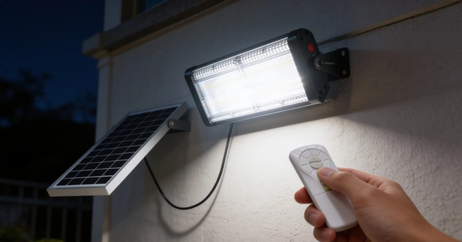
> Quick answer: Solar lamps with PIR motion sensors and dusk-to-dawn photocells operate through staged illumination states: full brightness at dusk (2000 lumens), low power after two hours, and motion-triggered bursts. This system extends nightly runtime by conserving energy [9][17].
In Romania, where solar lamps are increasingly popular for outdoor lighting solutions, understanding how these systems work is crucial. Solar lamps equipped with PIR (Passive Infrared) motion sensors and dusk-to-dawn photocells use a layered decision-making process to manage power efficiently throughout the night.
How PIR Sensors and Photocells Work Together
A solar lamp system employing both a PIR motion sensor and a dusk-to-dawn photocell operates through dynamic stages of illumination. The journey from dusk till dawn involves three primary states: full brightness, low power, and standby with motion detection [9][17].
Full Brightness Mode
At dusk, the photocell detects sufficient darkness and triggers the lamp to turn on at full 2000-lumen output [24]. This initial state is set at 100% factory default brightness until two hours post-dusk [9][17].
Low Power State
After two hours, the system automatically dims to a lower energy-conserving level (e.g., 25% brightness) based on a time-based schedule. The processor monitors and adjusts based on absolute hours or as fractions of the dusk-to-dawn cycle [2][7]. This staged dimming ensures efficient power usage [8].
Standby Mode with Motion Detection
In standby mode, the PIR sensor remains active to detect human motion up to 10 meters away. If motion is detected, it triggers a full-power burst for a fixed duration (typically 10 minutes) before dimming back down to low level over one minute [9][17]. This adaptive response ensures timely illumination without prolonged high power consumption.
Seasonal Adjustments and Pre-Dawn Boost
The system’s logic can dynamically adjust based on solar time indicators, such as „solar midnight” or „midway between solar midnight and solar noon,” to adapt to changing daylight durations [2][7]. Additionally, the lamp brightens back to full output 30 minutes before dawn, ensuring visibility during the transition to daylight [9][17].
Adaptive Timeout Logic
A key innovation is the adaptive timeout logic in PIR sensors. The duration of the full-brightness response can be dynamically adjusted based on motion frequency—extending the on-time with frequent motion and shortening it when rare [14]. This intelligent mechanism optimizes energy usage compared to static timers that lead to premature shutoff or unnecessary waste [13].
Efficiency Benefits
The convergence of time-based dimming and motion-activated full brightness can reduce energy consumption by up to 60% compared to systems running at full power all night. The photocell ensures the lamp is active only during darkness, preventing daytime activation and battery drain [21]. Meanwhile, PIR sensors ensure that energy is not wasted when no one is present [3].
Comparison Table: Solar Lamp Settings
| Mode | Brightness Level | Duration |
|–––––|––––––|––––––|
| Full Bright | 100% (2000 lumens) | First two hours |
| Low Power | 25% | After two hours |
| Motion Burst | 100% | 10 minutes |
Key Takeaways
- Solar lamps with PIR sensors and photocells operate through a staged illumination process to extend runtime.
- The system transitions from full brightness at dusk, to low power post-dusk, and uses motion detection for bursts of full output [9][17].
- Adaptive timeout logic optimizes energy use by adjusting the duration based on motion frequency.
Frequently Asked Questions
„`json
[
{
„q”: „What triggers the initial full brightness mode?”,
„a”: „The initial full brightness mode is triggered at dusk when the photocell detects sufficient darkness [24].”
},
{
„q”: „How long does the lamp stay in low power after dimming?”,
„a”: „After two hours post-dusk, the lamp automatically dims to a lower 25% brightness level and remains there until motion is detected or dawn approaches [9][17].”
},
{
„q”: „What happens when motion is detected during the low power phase?”,
„a”: „When motion is detected during the low power phase, the lamp triggers a full-power burst for 10 minutes before dimming back down over one minute. This ensures visibility without prolonged high power consumption [9][17].”
}
]
„`
References
- [2] US20170055324A1_-_Apparatus_retrofit_kit_and_-_Google_Patents__f5522dda — patent
source passage
or dimming schedule. – the at least one processor can monitor for occurrence of a defined event after or following the turn ON event. – the at least one processor can monitor for occurrence of a passage of a defined duration after the turn ON event. – the defined duration may be specified by the illumination adjustment or dimming schedule, for example in terms of seconds, minutes, hours, percentage or fraction of total dusk-to-dawn cycle, or clock cycles of a timer or clock following the turn ON event. – the at least one processor can monitor for occurrence of a defined time (e.g., real world time) or condition (e.g., solar midnight, solar noon, midway between solar midnight and solar noon). – the at least one processor causes the light emitted or produced by the light source(s) of the luminaire(s) to be reduced to a second non-zero level of illumination, as specified by the illumination adjustment or dimming schedule, for example as specified by a selected illumination adjustment or dimming schedule. – the circuitry of the dusk/dawn sensor or the control system or a component thereof determines whether motion is sensed. – the motion sensing may operate concurrently during a portion or all of the remainder of the method, for example as a parallel routine or thread, for example executed by the legacy motion sensor in parallel with the retrofit control system. – the motion sensing may be performed by the at least one processor of a retrofit luminaire control system, or may be p
- [3] US20120020060A1_-_Energy-efficient_solar-powered_-_Google_Patents__619c8cff — patent
source passage
air. – Motion sensors detect movement during low light or nighttime conditions. There are three motion sensors mounted on the light pole. They are low profile and unobtrusive (black body blends in with the pole). The motion detectors are capable of sensing motion out to 10 meters. Yet they have high a high S/N ratio and are low power consumption. Any motion detected is fed back to the controller board which then decides how to brighten the illumination of the LED's. Key variables in the algorithms include the current state of illumination and the battery voltage. – the preferred motion sensors are Panasonic's Model AMN14111 “black”. – the photocell detects the ambient light conditions, and is primarily active within the system around dusk and dawn. Detected light level is used to adjust the resistance of the photodetector in the photocell circuitry. – the control board senses the change in resistance of the photocell and uses it to determine when to turn the luminaire on (generally at dusk) and when to turn the luminaire off (generally at dawn). – the photocell is a twist-lock mounted device that mounts onto standard photocell interfaces on the top of light fixture boxes. – the electronics are conformally coated to withstand environmental extremes and are enclosed inside a UV resistant, high impact polypropylene case. It is also rated to operate from ⁇ 40 deg C. to +70 deg C. – the current photocell is the Fisher-Pierce 7760-ESS. – the wiring harness connects the batteries in
- [7] US20170055324A1_-_Apparatus_retrofit_kit_and_-_Google_Patents__f5522dda — patent
source passage
event after or following the turn ON event. – the at least one processor can monitor for occurrence of a passage of a defined duration after the turn ON event. – the defined duration may be specified by the illumination adjustment or dimming schedule, for example in terms of seconds, minutes, hours, percentage or fraction of total dusk-to-dawn cycle, or clock cycles of a timer or clock following the turn ON event. – the at least one processor can monitor for occurrence of a defined time (e.g., real world time) or condition (e.g., solar midnight, solar noon, midway between solar midnight and solar noon). – the at least one processor causes the light emitted or produced by the light source(s) of the luminaire(s) to be reduced to a second non-zero level of illumination, as specified by the illumination adjustment or dimming schedule, for example as specified by a selected illumination adjustment or dimming schedule. – the at least one processor or other circuitry determines whether motion is sensed. – the motion sensing may operate concurrently during a portion or all of the remainder of the method, for example as a parallel routine or thread. – the motion sensing may be performed by the at least one processor of a retrofit luminaire control system, or may be performed by a motion sensor which is a legacy component of the luminaire. – the motion sensing may rely on signals from a passive infrared (PIR) image sensor or a non-PIR image sensor (e.g., camera with detection of frame-
- [8] Solar_Street_Light_From_Germany__Why_90_of_Solar_Street_Light_Projects_Fail_Get_Professional_Solutions_DEL_Illumi__yw1s3KMKtQc — youtube
source passage
Many systems run at 100% power all night, which drains the battery by midnight. Without smart dimming or motion sensors, the system is inefficient and prone to early shut-offs. Our intelligent controllers use PIR motion sensors and smart time control. The light dims when no one is around and brightens to 100% when motion is detected. This saves 60% more energy and ensures light throughout the night. Why risk your reputation with low-quality components? Our solar lights are engineered in Dresden, Germany and manufactured in China. This ensures European quality standards at a price that keeps your project budget on track. When you choose DEL, you are investing in IP66 waterproofing, intelligent PIR motion sensors, and smart dimming technology. We solve the problems before they happen. Choosing the right solar street light isn't just about price. The technology behind it makes the real difference. Don't waste your investment on failed projects. Avoid common mistakes and ensure long-lasting reliable performance. Choose Dell Illumination Company Limited for trusted quality. Visit today solar-led-street-light.com.
- [9] WO2010057138A2_-_Energy-efficient_solar-powered_outdoor_lighting__593d23e6 — patent
source passage
is turned on & off by the photocell. [0276] Photocell turns the light on at 100% at dusk & remains on for 2 hours, at which time the light dims down to 25% power over the next minute. The light remains at the dimmed down light level state until the motion sensor is activated, at which time the light is brought back up to 100% for 10 minutes. The light then dims back down to 25% power over the next minute. The light dims back up to 100% 30 minutes pre-dawn and remains on until the photocell shuts the light off. Example 2, under Version C programming: [0277] Starting battery voltage Vsb = 12.0 V; Ending battery voltage Veb = 11.3 V; Factory pre-sets for Tk = 120 & Tn = 30 (dusk 2 hrs & pre-dawn 0.5 hr.); Dp=0.25; Mode = E3; and Light is turned on & off by the photocell. [0278] Photocell turns the light on at 100% at dusk & remains on for 2 hours, at which time the light dims down to 12.5% power (50% of Dp) over the next minute. The light remains at the dimmed down light level state until the motion sensor is activated, at which time the light is brought back up to 80% for 4 minutes. The light then dims back down to 12.5% power over the next minute. The light dims back up to 100% 0.5 hr. predawn and remains on until the photocell shuts the light off. Charging Circuit: [0279] A minimum Ah threshold will be set to eliminate noise that could create false counts on the Ah Min and Ah Hours readings. Test/Diagnostic Capabilities: [0280] The following numbered list comprises requests i
- [13] US20060125624A1_-_Passive_infrared_motion_sensor_-_Google_Patents__7c4b55fc — patent
source passage
enough to cover the interval between two successive movements which can be registered by the sensor. As the time delay between the intervals increases, the operation of the PIR occupancy sensor becomes more reliable because premature turn off of the lights is further minimized. But, because the lights are on for a longer period of time, the savings realized in energy use is decreased. – In this invention, and referring to FIG. 1 , theoccupancy sensor 10 can be in the form of a wall switch having one or two PIR sensors coupled to send signals to a two stage amplifier-filter which includesphoto sensor circuitry 12. Signals from the amplifier-filter andphoto sensor circuitry 12 are directed toprocessor 14, and time delay and ambientlight adjustment circuit 16 is provided to manually set the time delay and adjust for ambient light conditions. EEPROMmemory chip 18 is coupled toprocessor 14 and stores information about previous settings.Relay 20 is controlled byprocessor 14 to either make or break the electrical connection within a current carrying line to control the flow of power to the lights in a room. AnLED indicator 22 is coupled to the two stage amplifier-filter and photo sensor circuitry to indicate when thePIR sensors 10 register occupancy in the room. Although an LED is shown as a visual means of indication, it should be understood that other means of indication can be provided such as an audio buzzer. – The PIR sensors 10 monitor a room for a change of IR radiation, and
- [14] US20060125624A1_-_Passive_infrared_motion_sensor_-_Google_Patents__7c4b55fc — patent
source passage
to be large to reduce the possibility that the lights will turn off during occupancy, so will the use of electricity be increased as the lights are now on for a longer time. Usually, the time delay in PIR occupancy sensors is preset to a constant value during installation and, therefore, may not be set to optimally control the lighting in the room. – What is needed is a PIR sensor which provides an improved method of controlling the on-off time cycle of lights in a room. – The intelligent PIR sensor here disclosed has variable adaptive timeout. When a person first walks into the room and, after a very short time, walks out of the room, the PIR sensor operates with a short timeout. This allows the room lights to be turned off relatively soon after the person leaves the room and is here referred to as the “walk-through” mode. This mode helps to reduce the use of energy. When, however, a person lingers in the room, the PIR sensor switches to another mode of operation where the timeout does not stay constant but increases or decreases where the change is determined by the frequency that the sensor detects motion in the room and the amplitude and/or duration of the signal of the detected motion. – In one aspect of the invention, a method of controlling the lights in a room with an occupancy sensor is provided. An initial timeout period is set for an occupancy sensor to operate a light before the timeout period expires upon sensing motion. A signal representing a motion sensed is c
- [17] WO2010057138A2_-_Energy-efficient_solar-powered_outdoor_lighting__593d23e6 — patent
source passage
initially coated with dielectric grease to prevent oxidation and corrosion of the metal contacts. All main power lines (from solar collector to charge controller & from charge controller to load and batteries) are fused (5 amps). – the photocell turns on the light at 100% (factory preset) normal power. It stays at 100% for two hours (factory preset) then dims down to 25% brightness (factory preset) for the balance of the night w/ motion sensor over-ride. If motion is detected it immediately brightens up to 100% for 10 minutes after the last-detected motion. It then dims back down to the lower setting over one minute. Towards dawn, the light will brighten back up to full brightness approximately 30 minutes (factory preset) prior to dawn. When the photocell threshold for dawn is crossed, the light will turn off. – Figure 47 portrays examples of how system conditions can be utilized to determine the appropriate energy modes based on current states to modify power delivered, to the light or other loads, beyond or instead of the "normal" changes over time shown in Figure 46. – the voltage of the batteries (on the right of the figure) is one indicator of how much energy is available in the battery storage. As the battery voltage drops, the energy mode is adjusted so that energy can be conserved. – the Ah decision block is referring to the solar production (in Amp-Hours, Ah) from the previous day. This Ah information is also an indicator of whether or not energy needs to be conserve
- [21] US4982176A_-_Solar_powered_lighting_and_alarm_-_Google_Patents__2a7f5e5c — patent
source passage
to prevent the system from turning on lamp 40 unless the dual requirements of low background light level (i.e darkness) sensed by the photocell 80, and the detection of a moving object sensed by PIR detector 50 are met. In this manner, the battery charge is maintained, as charge is not wasted by lighting lamp 40 during the daytime. Similarly, the adjustable timer 74 part of the light control logic and timing circuit 70, which is indicated as a potentiometer, but which may take any of numerous forms well known in the arts, is utilized to limit the drain on battery 30. Effectively, timer 74 closes the circuit between the battery and the lamp 40 for a predetermined period of time (e.g. three minutes) when the AND gate provides a positive output. After the predetermined period of time, (which can be set in the preferred embodiment for between thirty seconds and thirty minutes by the user via the turning of a knob), the timer 74 opens the circuit between the battery 30 and the lamp 40, thereby turning off the lamp 40 and having the charge on the battery 30. The lamp 40 of the system 10 is a bulb with a rating of at least one, and preferably three to five watts, and is powered by battery 30 via light control circuit 70. The lamp is associated with spherical reflectors or mirrors 72a and 72b which reflect the relatively large amount of light towards the area where it is needed With the reflectors 72 and the relatively high watt bulb, high brightness and efficient illumination are ac
- [24] US20210029802A1_-_System_For_Dynamic_Switching_Control_Of_A__778bbef8 — patent
source passage
to (i) turn on a luminaire at dusk i.e. when the measured light intensity falls below a pre-determined threshold light intensity and (ii) turn off the luminaire at dawn when the measured light intensity exceeds the pre-determined threshold light intensity. The photocells utilize semiconductors to control the flow of electric current through them. When the semiconductors are exposed to a certain level of light, current starts to flow through them and the luminaire is shut off. Some of these photocell sensors allow a user to choose the light level that will activate the semiconductor. As the light fades during the evening, the current flow reduces and stops eventually, causing the luminaire to turn on. – These systems are thus effective in reducing the lighting energy consumption. However, with time, contaminants such as dust, snow, and mud settle on the surface of the photocells. The photocells are generally incapable of detecting such contaminants. The settlement of contaminants on the surface of the photocells causes the light intensity measured by the photocells to be lower than the actual ambient light intensity. This leads to false triggering of the luminaries, which is not desired. – Thus, since the threshold light intensity is constant (factory set), the system turns on the luminaries even when there is sufficient ambient light, thereby leading to wastage of energy. Further, carrying out maintenance and cleaning of such luminaries is also not practical as the photocells
or dimming schedule. – the at least one processor can monitor for occurrence of a defined event after or following the turn ON event. – the at least one processor can monitor for occurrence of a passage of a defined duration after the turn ON event. – the defined duration may be specified by the illumination adjustment or dimming schedule, for example in terms of seconds, minutes, hours, percentage or fraction of total dusk-to-dawn cycle, or clock cycles of a timer or clock following the turn ON event. – the at least one processor can monitor for occurrence of a defined time (e.g., real world time) or condition (e.g., solar midnight, solar noon, midway between solar midnight and solar noon). – the at least one processor causes the light emitted or produced by the light source(s) of the luminaire(s) to be reduced to a second non-zero level of illumination, as specified by the illumination adjustment or dimming schedule, for example as specified by a selected illumination adjustment or dimming schedule. – the circuitry of the dusk/dawn sensor or the control system or a component thereof determines whether motion is sensed. – the motion sensing may operate concurrently during a portion or all of the remainder of the method, for example as a parallel routine or thread, for example executed by the legacy motion sensor in parallel with the retrofit control system. – the motion sensing may be performed by the at least one processor of a retrofit luminaire control system, or may be p
air. – Motion sensors detect movement during low light or nighttime conditions. There are three motion sensors mounted on the light pole. They are low profile and unobtrusive (black body blends in with the pole). The motion detectors are capable of sensing motion out to 10 meters. Yet they have high a high S/N ratio and are low power consumption. Any motion detected is fed back to the controller board which then decides how to brighten the illumination of the LED's. Key variables in the algorithms include the current state of illumination and the battery voltage. – the preferred motion sensors are Panasonic's Model AMN14111 “black”. – the photocell detects the ambient light conditions, and is primarily active within the system around dusk and dawn. Detected light level is used to adjust the resistance of the photodetector in the photocell circuitry. – the control board senses the change in resistance of the photocell and uses it to determine when to turn the luminaire on (generally at dusk) and when to turn the luminaire off (generally at dawn). – the photocell is a twist-lock mounted device that mounts onto standard photocell interfaces on the top of light fixture boxes. – the electronics are conformally coated to withstand environmental extremes and are enclosed inside a UV resistant, high impact polypropylene case. It is also rated to operate from ⁇ 40 deg C. to +70 deg C. – the current photocell is the Fisher-Pierce 7760-ESS. – the wiring harness connects the batteries in
event after or following the turn ON event. – the at least one processor can monitor for occurrence of a passage of a defined duration after the turn ON event. – the defined duration may be specified by the illumination adjustment or dimming schedule, for example in terms of seconds, minutes, hours, percentage or fraction of total dusk-to-dawn cycle, or clock cycles of a timer or clock following the turn ON event. – the at least one processor can monitor for occurrence of a defined time (e.g., real world time) or condition (e.g., solar midnight, solar noon, midway between solar midnight and solar noon). – the at least one processor causes the light emitted or produced by the light source(s) of the luminaire(s) to be reduced to a second non-zero level of illumination, as specified by the illumination adjustment or dimming schedule, for example as specified by a selected illumination adjustment or dimming schedule. – the at least one processor or other circuitry determines whether motion is sensed. – the motion sensing may operate concurrently during a portion or all of the remainder of the method, for example as a parallel routine or thread. – the motion sensing may be performed by the at least one processor of a retrofit luminaire control system, or may be performed by a motion sensor which is a legacy component of the luminaire. – the motion sensing may rely on signals from a passive infrared (PIR) image sensor or a non-PIR image sensor (e.g., camera with detection of frame-
Many systems run at 100% power all night, which drains the battery by midnight. Without smart dimming or motion sensors, the system is inefficient and prone to early shut-offs. Our intelligent controllers use PIR motion sensors and smart time control. The light dims when no one is around and brightens to 100% when motion is detected. This saves 60% more energy and ensures light throughout the night. Why risk your reputation with low-quality components? Our solar lights are engineered in Dresden, Germany and manufactured in China. This ensures European quality standards at a price that keeps your project budget on track. When you choose DEL, you are investing in IP66 waterproofing, intelligent PIR motion sensors, and smart dimming technology. We solve the problems before they happen. Choosing the right solar street light isn't just about price. The technology behind it makes the real difference. Don't waste your investment on failed projects. Avoid common mistakes and ensure long-lasting reliable performance. Choose Dell Illumination Company Limited for trusted quality. Visit today solar-led-street-light.com.
is turned on & off by the photocell. [0276] Photocell turns the light on at 100% at dusk & remains on for 2 hours, at which time the light dims down to 25% power over the next minute. The light remains at the dimmed down light level state until the motion sensor is activated, at which time the light is brought back up to 100% for 10 minutes. The light then dims back down to 25% power over the next minute. The light dims back up to 100% 30 minutes pre-dawn and remains on until the photocell shuts the light off. Example 2, under Version C programming: [0277] Starting battery voltage Vsb = 12.0 V; Ending battery voltage Veb = 11.3 V; Factory pre-sets for Tk = 120 & Tn = 30 (dusk 2 hrs & pre-dawn 0.5 hr.); Dp=0.25; Mode = E3; and Light is turned on & off by the photocell. [0278] Photocell turns the light on at 100% at dusk & remains on for 2 hours, at which time the light dims down to 12.5% power (50% of Dp) over the next minute. The light remains at the dimmed down light level state until the motion sensor is activated, at which time the light is brought back up to 80% for 4 minutes. The light then dims back down to 12.5% power over the next minute. The light dims back up to 100% 0.5 hr. predawn and remains on until the photocell shuts the light off. Charging Circuit: [0279] A minimum Ah threshold will be set to eliminate noise that could create false counts on the Ah Min and Ah Hours readings. Test/Diagnostic Capabilities: [0280] The following numbered list comprises requests i
enough to cover the interval between two successive movements which can be registered by the sensor. As the time delay between the intervals increases, the operation of the PIR occupancy sensor becomes more reliable because premature turn off of the lights is further minimized. But, because the lights are on for a longer period of time, the savings realized in energy use is decreased. – In this invention, and referring to FIG. 1 , theoccupancy sensor 10 can be in the form of a wall switch having one or two PIR sensors coupled to send signals to a two stage amplifier-filter which includesphoto sensor circuitry 12. Signals from the amplifier-filter andphoto sensor circuitry 12 are directed toprocessor 14, and time delay and ambientlight adjustment circuit 16 is provided to manually set the time delay and adjust for ambient light conditions. EEPROMmemory chip 18 is coupled toprocessor 14 and stores information about previous settings.Relay 20 is controlled byprocessor 14 to either make or break the electrical connection within a current carrying line to control the flow of power to the lights in a room. AnLED indicator 22 is coupled to the two stage amplifier-filter and photo sensor circuitry to indicate when thePIR sensors 10 register occupancy in the room. Although an LED is shown as a visual means of indication, it should be understood that other means of indication can be provided such as an audio buzzer. – The PIR sensors 10 monitor a room for a change of IR radiation, and
to be large to reduce the possibility that the lights will turn off during occupancy, so will the use of electricity be increased as the lights are now on for a longer time. Usually, the time delay in PIR occupancy sensors is preset to a constant value during installation and, therefore, may not be set to optimally control the lighting in the room. – What is needed is a PIR sensor which provides an improved method of controlling the on-off time cycle of lights in a room. – The intelligent PIR sensor here disclosed has variable adaptive timeout. When a person first walks into the room and, after a very short time, walks out of the room, the PIR sensor operates with a short timeout. This allows the room lights to be turned off relatively soon after the person leaves the room and is here referred to as the “walk-through” mode. This mode helps to reduce the use of energy. When, however, a person lingers in the room, the PIR sensor switches to another mode of operation where the timeout does not stay constant but increases or decreases where the change is determined by the frequency that the sensor detects motion in the room and the amplitude and/or duration of the signal of the detected motion. – In one aspect of the invention, a method of controlling the lights in a room with an occupancy sensor is provided. An initial timeout period is set for an occupancy sensor to operate a light before the timeout period expires upon sensing motion. A signal representing a motion sensed is c
initially coated with dielectric grease to prevent oxidation and corrosion of the metal contacts. All main power lines (from solar collector to charge controller & from charge controller to load and batteries) are fused (5 amps). – the photocell turns on the light at 100% (factory preset) normal power. It stays at 100% for two hours (factory preset) then dims down to 25% brightness (factory preset) for the balance of the night w/ motion sensor over-ride. If motion is detected it immediately brightens up to 100% for 10 minutes after the last-detected motion. It then dims back down to the lower setting over one minute. Towards dawn, the light will brighten back up to full brightness approximately 30 minutes (factory preset) prior to dawn. When the photocell threshold for dawn is crossed, the light will turn off. – Figure 47 portrays examples of how system conditions can be utilized to determine the appropriate energy modes based on current states to modify power delivered, to the light or other loads, beyond or instead of the "normal" changes over time shown in Figure 46. – the voltage of the batteries (on the right of the figure) is one indicator of how much energy is available in the battery storage. As the battery voltage drops, the energy mode is adjusted so that energy can be conserved. – the Ah decision block is referring to the solar production (in Amp-Hours, Ah) from the previous day. This Ah information is also an indicator of whether or not energy needs to be conserve
to prevent the system from turning on lamp 40 unless the dual requirements of low background light level (i.e darkness) sensed by the photocell 80, and the detection of a moving object sensed by PIR detector 50 are met. In this manner, the battery charge is maintained, as charge is not wasted by lighting lamp 40 during the daytime. Similarly, the adjustable timer 74 part of the light control logic and timing circuit 70, which is indicated as a potentiometer, but which may take any of numerous forms well known in the arts, is utilized to limit the drain on battery 30. Effectively, timer 74 closes the circuit between the battery and the lamp 40 for a predetermined period of time (e.g. three minutes) when the AND gate provides a positive output. After the predetermined period of time, (which can be set in the preferred embodiment for between thirty seconds and thirty minutes by the user via the turning of a knob), the timer 74 opens the circuit between the battery 30 and the lamp 40, thereby turning off the lamp 40 and having the charge on the battery 30. The lamp 40 of the system 10 is a bulb with a rating of at least one, and preferably three to five watts, and is powered by battery 30 via light control circuit 70. The lamp is associated with spherical reflectors or mirrors 72a and 72b which reflect the relatively large amount of light towards the area where it is needed With the reflectors 72 and the relatively high watt bulb, high brightness and efficient illumination are ac
to (i) turn on a luminaire at dusk i.e. when the measured light intensity falls below a pre-determined threshold light intensity and (ii) turn off the luminaire at dawn when the measured light intensity exceeds the pre-determined threshold light intensity. The photocells utilize semiconductors to control the flow of electric current through them. When the semiconductors are exposed to a certain level of light, current starts to flow through them and the luminaire is shut off. Some of these photocell sensors allow a user to choose the light level that will activate the semiconductor. As the light fades during the evening, the current flow reduces and stops eventually, causing the luminaire to turn on. – These systems are thus effective in reducing the lighting energy consumption. However, with time, contaminants such as dust, snow, and mud settle on the surface of the photocells. The photocells are generally incapable of detecting such contaminants. The settlement of contaminants on the surface of the photocells causes the light intensity measured by the photocells to be lower than the actual ambient light intensity. This leads to false triggering of the luminaries, which is not desired. – Thus, since the threshold light intensity is constant (factory set), the system turns on the luminaries even when there is sufficient ambient light, thereby leading to wastage of energy. Further, carrying out maintenance and cleaning of such luminaries is also not practical as the photocells