
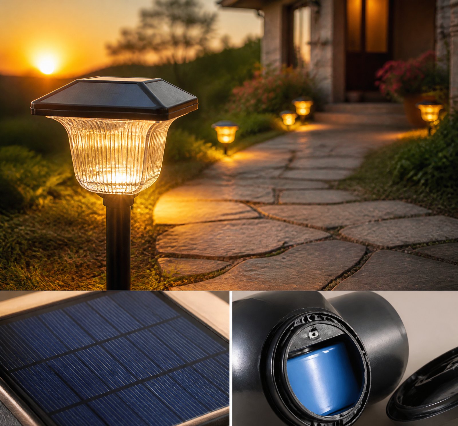
> Quick answer: The typical failure mechanisms for polycrystalline mini-panels in garden lights include microcracks, delamination, and discoloration. These issues arise from environmental stressors like hail and frost, as well as manufacturing quality and material choices [3][6].
Introduction
Polycrystalline solar lamps have become a popular choice for Romanian gardens due to their cost-effectiveness and ease of installation. However, understanding the potential failure mechanisms is crucial for ensuring longevity and performance. Let’s delve into the common issues like microcracks, delamination, and discoloration, and how they affect garden lights under Romanian weather conditions.
Microcracks: A Well-Documented Failure Mode
Microcracks in polycrystalline mini-panels are a significant issue, often originating from latent defects during manufacturing or developing over time due to thermal stress, hail impact, or mechanical damage [3][6]. These cracks disrupt electrical continuity and can lead to hot-spot heating when current flow is interrupted in fractured cells [11][15].
The risk of microcracking increases with thermal cycling, where repeated expansion and contraction from temperature fluctuations induce mechanical fatigue. This process is particularly challenging in Romanian regions with significant diurnal and seasonal temperature swings [2][10]. While the frequency under specific Romanian conditions isn’t quantified, it remains a critical concern.
Delamination: A Growing Concern
Delamination—the separation of encapsulant from glass or backsheet—is another common failure mode. Historically more prevalent in early-generation modules, delamination still poses risks due to moisture ingress, photothermal aging, or differential thermal and humidity expansion [3][6][8][9]. Recent visual inspection failures linked to changes in encapsulant materials suggest that even if less frequent than before, it remains a potential issue in high-temperature environments or where moisture penetrates [8][9].
The sources do not specify whether polycrystalline mini-panels are more susceptible to delamination than monocrystalline ones nor provide data on its occurrence under Romanian winter conditions. However, the risk of moisture ingress is heightened by poor sealing and thermal mismatches, leading to corrosion or short circuits [19].
Discoloration: A Precursor to Degradation
Discoloration, particularly of the encapsulant (EVA), is another failure mechanism noted in field evaluations. Prolonged UV exposure and heat can cause EVA discoloration, reducing light transmission and panel efficiency [18]. While not explicitly tied to polycrystalline garden lights, this degradation contributes to broader module failures like delamination and short circuits [3][6].
Discoloration may be a precursor to more serious issues but lacks specific quantification for small solar lamps in Romanian conditions. This implies that while discoloration is noted as a failure type, its frequency remains undefined.
Hail and Frost Conditions: Impact on Garden Lights
Hail can cause significant damage to garden lights by breaking glass or causing cell cracking, especially in modules with thinner glass [3][6][13][14]. Thinner glass, used to reduce weight and cost, increases breakage rates due to thermal cycling and mechanical loads, even under normal temperature changes [20].
Frost exacerbates thermal stress, particularly through ice formation and ground moisture. While snow typically slides off panels due to their warmth, improper removal can cause permanent damage [7][10]. Frost-induced seal failure allows moisture ingress, leading to corrosion or short circuits [19].
Cost-Cutting Manufacturing and Its Risks
A notable finding is that increased frequency of spontaneous glass breakage is linked not only to environmental extremes but also to cost-cutting measures like thinner glass and reduced encapsulant at module edges [20]. This underscores the role of manufacturing consistency over local weather patterns in panel failure rates.
Key Takeaways
- Microcracks, delamination, and discoloration are primary failure mechanisms for polycrystalline mini-panels.
- Hail and frost conditions can exacerbate these issues through thermal cycling and mechanical stress.
- Manufacturing choices, such as thinner glass and reduced encapsulant, increase the risk of spontaneous breakage.
Frequently Asked Questions
„`json
[
{
„q”: „What causes microcracks in solar panels?”,
„a”: „Microcracks can originate from latent defects during manufacturing or develop over time due to thermal stress, hail impact, or mechanical damage [3][6].”
},
{
„q”: „How does delamination affect polycrystalline mini-panels?”,
„a”: „Delamination occurs when the encapsulant separates from glass or backsheet. This is driven by moisture ingress, photothermal aging, or differential thermal and humidity expansion [3][6][8].”
},
{
„q”: „What role does Romanian weather play in solar lamp failures?”,
„a”: „Romanian hail and frost conditions can cause mechanical stress, leading to glass breakage, cell cracking, and moisture ingress that exacerbate failure mechanisms [7][10].”
}
]
„`
References
- [2] How_long_do_residential_solar_panels_last_pv_magazine_International__a1e59f16 — authority
source passage
materials in their glass, encapsulation, and diffusion barriers. All panels also suffer something called light-induced degradation (LID), in which panels lose efficiency within the first hours of being exposed to the sun. LID varies from panel to panel based on the quality of the crystalline silicon wafers, but usually results in a one-time, 1-3% loss in efficiency, said testing laboratory PVEL, PV Evolution Labs. Weathering The exposure to weather conditions is the main driver in panel degradation. Heat is a key factor in both real-time panel performance and degradation over time. Ambient heat negatively affects the performance and efficiency of electrical components, according to NREL. By checking the manufacturer’s data sheet, a panel’s temperature coefficient can be found, which will demonstrate the panel’s ability to perform in higher temperatures. The coefficient explains how much real-time efficiency is lost by each degree Celsius increase above the standard temperature of 25 degrees Celsius. For example, a temperature coefficient of -0.353% means that for every degree Celsius above 25, 0.353% of total production capability is lost. Heat exchange drives panel degradation through a process called thermal cycling. When it is warm, materials expand, and when the temperature lowers, they contract. This movement slowly causes microcracks to form in the panel over time, lowering output. In its annual Module Score Card study, PVEL analyzed 36 operational solar projects in Ind
- [3] Degradation_and_Failure_Modes_PVEducation__a35d6651 — authority
source passage
plus "interconnect-busbars" allow the cell to continue functioning. Cell cracking can be caused by: – thermal stress; – hail; or – damage during processing and assembly, resulting in "latent cracks", which are not detectable on manufacturing inspection, but appear sometime later. Interconnect Open-Circuits Fatigue due to cyclic thermal stress and wind loading leads to interconnect open circuit failures. Module Open-Circuits Open circuit failures also occur in the module structure, typically in the bus wiring or junction box. Module Short-Circuits Although each module is tested before sale, module short circuits are often the result of manufacturing defects. They occur due to insulation degradation with weathering, resulting in delamination, cracking or electrochemical corrosion. Module Glass Breakage Shattering of the top glass surface can occur due to vandalism, thermal stress, handling, wind or hail. Module Delamination A common failure mode in early generations of modules, module delamination is now less of a problem. It is usually caused by reductions in bond strength, either environmentally induced by moisture or photothermal aging and stress which is induced by differential thermal and humidity expansion. Hot-Spot Failures Mismatched, cracked or shaded cells can lead to hot-spot failures, as discussed previously in Hot Spot Heating. By-Pass Diode Failure By-pass diodes, used to overcome cell mismatching problems, can themselves fail, usually due to overheating, often du
- [6] Degradation_and_Failure_Modes_PVEducation__c17f54a9 — authority
source passage
plus "interconnect-busbars" allow the cell to continue functioning. Cell cracking can be caused by: – thermal stress; – hail; or – damage during processing and assembly, resulting in "latent cracks", which are not detectable on manufacturing inspection, but appear sometime later. Interconnect Open-Circuits Fatigue due to cyclic thermal stress and wind loading leads to interconnect open circuit failures. Module Open-Circuits Open circuit failures also occur in the module structure, typically in the bus wiring or junction box. Module Short-Circuits Although each module is tested before sale, module short circuits are often the result of manufacturing defects. They occur due to insulation degradation with weathering, resulting in delamination, cracking or electrochemical corrosion. Module Glass Breakage Shattering of the top glass surface can occur due to vandalism, thermal stress, handling, wind or hail. Module Delamination A common failure mode in early generations of modules, module delamination is now less of a problem. It is usually caused by reductions in bond strength, either environmentally induced by moisture or photothermal aging and stress which is induced by differential thermal and humidity expansion. Hot-Spot Failures Mismatched, cracked or shaded cells can lead to hot-spot failures, as discussed previously in Hot Spot Heating. By-Pass Diode Failure By-pass diodes, used to overcome cell mismatching problems, can themselves fail, usually due to overheating, often du
- [7] How_long_do_rooftop_residential_solar_panels_last_-_pv_magazine_Global__7bebb092 — authority
source passage
air can flow beneath and cool the equipment. Light-colored materials can be used in panel construction to limit heat absorption. And components like inverters and combiners, whose performance is particularly sensitive to heat, should be located in shaded areas, suggested CED Greentech. The same goes for snow, which can cover panels during heavier storms, limiting output. Snow can also cause a dynamic mechanical load, degrading the panels. Typically, snow will slide off of panels, as they are slick and run warm, but in some cases a homeowner may decide to clear the snow off the panels. This must be done carefully, as scratching the glass surface of the panel would make a negative impact on output. Degradation is a normal, unavoidable part of a panel’s life. Proper installation, careful snow clearing, and careful panel cleaning can help with output, but ultimately, a solar panel is a technology with no moving parts, requiring very little maintenance. Setting standards To ensure a given panel is likely to live a long life and operate as planned, it must undergo standards testing for certification. Panels are subject to the International Electrotechnical Commission (IEC) testing, which apply to both mono- and polycrystalline panels. EnergySage said panels that achieve IEC 61215 standard are tested for electrical characteristics like wet leakage currents, and insulation resistance. They under go a mechanical load test for both wind and snow, and climate tests that check for weakne
- [8] Digging_into_delamination_distress_Why_too_many_PV_-_PV_Tech__e765367e — magazine
source passage
# Digging into delamination distress: Why too many PV modules are failing at the edges Source: Blog/Web URL: https://www.pv-tech.org/digging-into-delamination-distress-why-too-many-pv-modules-are-failing-at-the-edges/ Author: Jonathan Touriño Jacobo Date: 2025-11-05 Looks matter when it comes to PV modules. At Kiwa PVEL, our independent extended reliability testing has revealed an increase in the number of visual inspection failures over the last year, specifically related to delamination defects. As we’ve often noted, changes in an individual module’s unique Bill of Materials (BOM) can have big impacts to its long-term reliability and performance. As module producers update their manufacturing processes and deploy new types of encapsulant materials, and as more modules are deployed to high-temperature environments, issues related to delamination can arise that impact project safety and performance. Try Premium for just $1 – Full premium access for the first month at only $1 – Converts to an annual rate after 30 days unless cancelled – Cancel anytime during the trial period Premium Benefits – Expert industry analysis and interviews – Digital access to PV Tech Power journal – Exclusive event discounts Throughout our suite of testing, the Product Qualification Program (PQP), Kiwa PVEL conducts visual inspections of modules to identify issues that cause premature field failure. Modules are examined for delamination, corrosion, broken or cracked surfaces and other ‘major’ defects
- [9] Digging_into_delamination_distress_Why_too_many_PV_-_PV_Tech__e765367e — authority
source passage
# Digging into delamination distress: Why too many PV modules are failing at the edges Source: Blog/Web URL: https://www.pv-tech.org/digging-into-delamination-distress-why-too-many-pv-modules-are-failing-at-the-edges/ Author: Jonathan Touriño Jacobo Date: 2025-11-05 Looks matter when it comes to PV modules. At Kiwa PVEL, our independent extended reliability testing has revealed an increase in the number of visual inspection failures over the last year, specifically related to delamination defects. As we’ve often noted, changes in an individual module’s unique Bill of Materials (BOM) can have big impacts to its long-term reliability and performance. As module producers update their manufacturing processes and deploy new types of encapsulant materials, and as more modules are deployed to high-temperature environments, issues related to delamination can arise that impact project safety and performance. Try Premium for just $1 – Full premium access for the first month at only $1 – Converts to an annual rate after 30 days unless cancelled – Cancel anytime during the trial period Premium Benefits – Expert industry analysis and interviews – Digital access to PV Tech Power journal – Exclusive event discounts Throughout our suite of testing, the Product Qualification Program (PQP), Kiwa PVEL conducts visual inspections of modules to identify issues that cause premature field failure. Modules are examined for delamination, corrosion, broken or cracked surfaces and other ‘major’ defects
- [10] How_long_do_residential_solar_panels_last_pv_magazine_International__a1e59f16 — authority
source passage
in the panels, lowering output. Some racking solutions are optimized for high-wind areas, protecting the panels from strong uplift forces and limiting microcracking. Typically, the manufacturer’s datasheet will provide information on the max winds the panel is able to withstand. The same goes for snow, which can cover panels during heavier storms, limiting output. Snow can also cause a dynamic mechanical load, degrading the panels. Typically, snow will slide off of panels, as they are slick and run warm, but in some cases a homeowner may decide to clear the snow off the panels. This must be done carefully, as scratching the glass surface of the panel would make a negative impact on output. (Read: “Tips for keeping your rooftop solar system humming over the long term“) Degradation is a normal, unavoidable part of a panel’s life. Proper installation, careful snow clearing, and careful panel cleaning can help with output, but ultimately, a solar panel is a technology with no moving parts, requiring very little maintenance. Standards To ensure a given panel is likely to live a long life and operate as planned, it must undergo standards testing for certification. Panels are subject to the International Electrotechnical Commission (IEC) testing, which applies to both mono- and polycrystalline panels. EnergySage said panels that achieve IEC 61215 standard are tested for electrical characteristics like wet leakage currents, and insulation resistance. They undergo a mechanical load te
- [11] Digital Transformation in Ukraine — book
source passage
of a solar module arrangement is shown in the Figure 52.1 given below. Figure 52.1 Cross-sectional view of a solar module arrangement Identification of Cracks Depending on the size of the fracture, it is possible to classify cracks as macro- or micro cracks. Typically, a crack that is less than 30 m wide is referred to as a -crack. The cracks are categorized as facial or sub-facial cracks depending on where they are located. Facial cracks are cracks that appear on the silicon wafer’s surface [5]. These face fissures are difficult to measure with bare eyes owing to their size. Subfascial cracks are those that originate on a wafer’s surface and spread in the depth direction, or those that start on the surface and do the opposite [6]. Subfascial cracks may be additionally categorized as deep or shallow cracks depending on the severity of the fracture. Severe ohmic shunts may be caused by microcracks that are inherent in the beginning wafer or develop while fabrication before screen-printing metallization. When the operational current of a model surpasses the minimized short-circuit current of a fault cell, a module’s defective cell or group of cells may cause hot-spot overheating issues. Grunow et al. applied substantially changing fractures patterns to an exemplar cell module to ascertain the impact of the location of the fissures on the electrical properties of each of the cells [7]. Only a small power loss of less than 4% resulted if the fissures were parallel and located in
- [13] Ultimate_Guide_to_Solar_Panel_Maintenance_Family_Handyman__c7ef40e9 — reddit
source passage
# Solar Panel Maintenance Guide Source: Blog/Web URL: https://www.familyhandyman.com/article/solar-panel-maintenance-guide/ Author: Karuna Eberl Date: 2022-09-15 Solar Panel Maintenance Guide From droughts to blizzards, here's how to keep your residential solar panels performing at their peak. Solar panels are tough. A few years ago the Denver area experienced the most damaging hail storm in its history, yet the National Renewable Energy Laboratory and its 3,000-panel array escaped with only one cracked panel. More than 150,000 vehicles scarred by the golf-ball-size hail weren’t so fortunate. While residential solar panels can withstand some force, they do sometimes break. Furthermore, they require regular maintenance in order to maintain their solar power efficiency and to extend their lifespan. Here’s what to know about solar panels to keep them in tip-top shape. On This Page Solar panel maintenance includes cleaning the glass and periodically inspecting wires to be sure they aren’t exposed or deteriorating. Conditions to keep in mind include: – Dust and stains: Solar panels accumulate film on their glass over time, reducing efficiency. – Debris: Branches and leaves left by storms also reduce efficiency. “After a while, those can also create hotspots, causing panels to overheat,” says Yi Li, founder and CEO of Renogy, a renewable energy company. – Snow and ice: Accumulation on panels can cause under-cooling, which creates micro-cracks. Solar panel cleaning frequency is dete
- [14] Solar_module_glass_is_spontaneously_breaking_in_the_field__21d4e27b — magazine
source passage
tempered. Now, “we are regularly hearing about glass breakage in silicon modules.” Barnes acknowledges these reports are anecdotal, but there is also “a definite pattern.” “It used to be the case that modules would pass the IEC 61215 static load test with a big safety factor. Today, modules are either barely passing the base static load test or they are not passing with higher safety factors. Some new module designs are simply not passing the minimum static load test.” Module market context Large-format modules, and concerns about how to support them, are not new. The cover article of our Spring 2020 edition, “Mounting and Cracking” examined the structural durability issues inherent with large-format solar modules. But, as RETC notes in the intro of this report, we all might have understated or misunderstood all of the impacts: “The early warning efforts documented in our article, ‘Evaluating Large-Format PV Modules,’ are simultaneously prescient and naïve. While we had clearly identified a signal in our laboratory testing and field forensics—namely, structural vulnerabilities associated with newer module designs—we did not necessarily understand the root cause of the issue.” – Was the physical size of these new modules a problem? – Was solar market proliferation to blame for subjecting modules to previously unaccounted for environmental stresses? – Were our testing protocols and sequences inadequate to identify potential new failure modes and wear-out mechanisms? The questio
- [15] Digital Transformation in Ukraine — book
source passage
the module are frequently still functional [1]. Parts of the cell may become segregated from the external circuit when fractured metallization disrupts current flow, lowering the energy output of the cell. Power loss and heating can result from electrical mismatches between cells in the same series string [2]. This dissipation occasionally poses a risk to safety. These loads can damage the cell connectivity and reduce the electrical output of PV modules made of crystalline silicon, which can result in fractures and hotspots. Detecting changes in metallization resistance between cell fragments during variations in module temperature can be done via electroluminescence (EL) imaging. EL images exhibit great contrast over a fracture when damaged metallization obstructs current passage there. When the temperature of the module changes, cell pieces move. In some circumstances, the metallization’s irregular fracture surfaces allow it to continue to be electrically linked during this movement [3]. In other situations, electrical continuity is sporadic or nonexistent. These surfaces may come into touch and shift, resulting in wear and a gradual loss of electrical continuity. Operators of industrial PV systems have become more conscious of these loads during the past few years. The output power generated by the PV installations is continuously monitored and recorded, and it is compared to theoretical projections for health and safety precautions. Throughout their lifespan, PV modules a
- [18] Review_of_Failures_of_Photovoltaic_Modules_Final_-_IEA-PVPS__d13cf25e — authority
source passage
evaluation. Furthermore we introduce a signal transition method for the detection of defective circuits in installed PV modules. All methods are linked to the PV module failures which are able to be found with these methods. In the second part, the most common failures of PV modules are described in detail. In particular these failures are: delamination, back sheet adhesion loss, junction box failure, frame breakage, EVA discolouration, cell cracks, snail tracks, burn marks, potential induced degradation, disconnected cell and string interconnect ribbons, defective bypass diodes; and special failures of thin-film modules, such as micro arcs at glued connectors, shunt hot spots, front glass breakage, and back contact degradation. Where possible, the origin of the failure is explained. A reference to the characterisation method is given to identify the failure. If available, statistics of the failure type in the field and from accelerating aging tests are shown. For each failure, a description of safety issues and the influence on the power loss is given, including typical follow-up failure modes. In the third part, new test methods are proposed for detection of PV module failures in the field. A special focus is made on mechanical tests because many problems have arisen in the last few years from the mechanical loading of modules. These mechanical loads occur during transportation and from snow loads on modules mounted on an incline. Furthermore, testing for UV degradation of
- [19] US8585245B2_-_Systems_and_methods_for_sealing_-_Google_Patents__154e7e2e — patent
source passage
may cause problems and even malfunctions of lighting units which may include electronic and/or electrical components. Short circuit contacts may be caused by water or humidity which may destroy the electronic components such as switches or processors, thus decreasing the life span of the lighting fixtures and increasing the maintenance cost. Shielding the lighting units from these natural elements may become even more challenging as the rates of extension and contraction of different materials used for building the lighting fixtures may vary. This variation in extension and contraction rates between different materials may cause seals to crack along the interfaces of these materials. The cracks may provide openings for leakages, which may be even exacerbated by future contractions and expansions of materials as some parts of lighting units expand much more than other parts. – the present disclosure addresses these issues by providing a reliable and comprehensive enclosure system that seals a lighting fixture from outside elements. – the systems, apparatuses and techniques of the present disclosure provide a lasting seal for the lighting fixture regardless of the rates of expansion and contraction different materials may experience. – the systems, apparatuses and techniques described herein also allow for a water-tight seal regardless of sizes and lengths of enclosure components. – the solution presented may utilize one or more silicone gaskets in combination with one or more
- [20] Module_reliability_scorecard_reveals_widespread_quality_risk__c7271aa4 — magazine
source passage
up from just 7% in both the 2023 and 2024 scorecards, and that the load testing conducted as part of the Reliability Scorecard goes up to 1800 pascals of pressure, rather than the 2400 specified in IEC testing standards. “These are the types of conditions that with wind loads and snow loads can occur in the field. And I don’t know what other industry would accept a 20% failure rate.” These increased breakage rates have been seen in the field already in recent years, and the move to larger module formats, made with thinner glass, is one part of the problem. But it also comes down to cost cutting efforts as manufacturers look to cut back on material consumption in times of low prices for PV components. “Probably the biggest concerning aspect of this report is that module breakage has really increased, which has a direct correlation to cost cutting,” said Erion-Lorico. In some cases, lack of encapsulant material at the edge of a module was shown to be enough to cause glass breakage, with solder points on the glass creating stress concentration points. With these, even day-to-day temperature changes could be enough to cause glass to break at the edges. “There’s a range of causes, whether that’s glass strengthening issues, flaws within the glass, weaker frame designs, edge pinch on the laminates, poor frame sealant approaches, and more aggressive mounting systems,” Erion-Lorico added. The tests also showed an increase in overall failure rate, with products from 83% of manufacturer
materials in their glass, encapsulation, and diffusion barriers. All panels also suffer something called light-induced degradation (LID), in which panels lose efficiency within the first hours of being exposed to the sun. LID varies from panel to panel based on the quality of the crystalline silicon wafers, but usually results in a one-time, 1-3% loss in efficiency, said testing laboratory PVEL, PV Evolution Labs. Weathering The exposure to weather conditions is the main driver in panel degradation. Heat is a key factor in both real-time panel performance and degradation over time. Ambient heat negatively affects the performance and efficiency of electrical components, according to NREL. By checking the manufacturer’s data sheet, a panel’s temperature coefficient can be found, which will demonstrate the panel’s ability to perform in higher temperatures. The coefficient explains how much real-time efficiency is lost by each degree Celsius increase above the standard temperature of 25 degrees Celsius. For example, a temperature coefficient of -0.353% means that for every degree Celsius above 25, 0.353% of total production capability is lost. Heat exchange drives panel degradation through a process called thermal cycling. When it is warm, materials expand, and when the temperature lowers, they contract. This movement slowly causes microcracks to form in the panel over time, lowering output. In its annual Module Score Card study, PVEL analyzed 36 operational solar projects in Ind
plus "interconnect-busbars" allow the cell to continue functioning. Cell cracking can be caused by: – thermal stress; – hail; or – damage during processing and assembly, resulting in "latent cracks", which are not detectable on manufacturing inspection, but appear sometime later. Interconnect Open-Circuits Fatigue due to cyclic thermal stress and wind loading leads to interconnect open circuit failures. Module Open-Circuits Open circuit failures also occur in the module structure, typically in the bus wiring or junction box. Module Short-Circuits Although each module is tested before sale, module short circuits are often the result of manufacturing defects. They occur due to insulation degradation with weathering, resulting in delamination, cracking or electrochemical corrosion. Module Glass Breakage Shattering of the top glass surface can occur due to vandalism, thermal stress, handling, wind or hail. Module Delamination A common failure mode in early generations of modules, module delamination is now less of a problem. It is usually caused by reductions in bond strength, either environmentally induced by moisture or photothermal aging and stress which is induced by differential thermal and humidity expansion. Hot-Spot Failures Mismatched, cracked or shaded cells can lead to hot-spot failures, as discussed previously in Hot Spot Heating. By-Pass Diode Failure By-pass diodes, used to overcome cell mismatching problems, can themselves fail, usually due to overheating, often du
plus "interconnect-busbars" allow the cell to continue functioning. Cell cracking can be caused by: – thermal stress; – hail; or – damage during processing and assembly, resulting in "latent cracks", which are not detectable on manufacturing inspection, but appear sometime later. Interconnect Open-Circuits Fatigue due to cyclic thermal stress and wind loading leads to interconnect open circuit failures. Module Open-Circuits Open circuit failures also occur in the module structure, typically in the bus wiring or junction box. Module Short-Circuits Although each module is tested before sale, module short circuits are often the result of manufacturing defects. They occur due to insulation degradation with weathering, resulting in delamination, cracking or electrochemical corrosion. Module Glass Breakage Shattering of the top glass surface can occur due to vandalism, thermal stress, handling, wind or hail. Module Delamination A common failure mode in early generations of modules, module delamination is now less of a problem. It is usually caused by reductions in bond strength, either environmentally induced by moisture or photothermal aging and stress which is induced by differential thermal and humidity expansion. Hot-Spot Failures Mismatched, cracked or shaded cells can lead to hot-spot failures, as discussed previously in Hot Spot Heating. By-Pass Diode Failure By-pass diodes, used to overcome cell mismatching problems, can themselves fail, usually due to overheating, often du
air can flow beneath and cool the equipment. Light-colored materials can be used in panel construction to limit heat absorption. And components like inverters and combiners, whose performance is particularly sensitive to heat, should be located in shaded areas, suggested CED Greentech. The same goes for snow, which can cover panels during heavier storms, limiting output. Snow can also cause a dynamic mechanical load, degrading the panels. Typically, snow will slide off of panels, as they are slick and run warm, but in some cases a homeowner may decide to clear the snow off the panels. This must be done carefully, as scratching the glass surface of the panel would make a negative impact on output. Degradation is a normal, unavoidable part of a panel’s life. Proper installation, careful snow clearing, and careful panel cleaning can help with output, but ultimately, a solar panel is a technology with no moving parts, requiring very little maintenance. Setting standards To ensure a given panel is likely to live a long life and operate as planned, it must undergo standards testing for certification. Panels are subject to the International Electrotechnical Commission (IEC) testing, which apply to both mono- and polycrystalline panels. EnergySage said panels that achieve IEC 61215 standard are tested for electrical characteristics like wet leakage currents, and insulation resistance. They under go a mechanical load test for both wind and snow, and climate tests that check for weakne
# Digging into delamination distress: Why too many PV modules are failing at the edges Source: Blog/Web URL: https://www.pv-tech.org/digging-into-delamination-distress-why-too-many-pv-modules-are-failing-at-the-edges/ Author: Jonathan Touriño Jacobo Date: 2025-11-05 Looks matter when it comes to PV modules. At Kiwa PVEL, our independent extended reliability testing has revealed an increase in the number of visual inspection failures over the last year, specifically related to delamination defects. As we’ve often noted, changes in an individual module’s unique Bill of Materials (BOM) can have big impacts to its long-term reliability and performance. As module producers update their manufacturing processes and deploy new types of encapsulant materials, and as more modules are deployed to high-temperature environments, issues related to delamination can arise that impact project safety and performance. Try Premium for just $1 – Full premium access for the first month at only $1 – Converts to an annual rate after 30 days unless cancelled – Cancel anytime during the trial period Premium Benefits – Expert industry analysis and interviews – Digital access to PV Tech Power journal – Exclusive event discounts Throughout our suite of testing, the Product Qualification Program (PQP), Kiwa PVEL conducts visual inspections of modules to identify issues that cause premature field failure. Modules are examined for delamination, corrosion, broken or cracked surfaces and other ‘major’ defects
# Digging into delamination distress: Why too many PV modules are failing at the edges Source: Blog/Web URL: https://www.pv-tech.org/digging-into-delamination-distress-why-too-many-pv-modules-are-failing-at-the-edges/ Author: Jonathan Touriño Jacobo Date: 2025-11-05 Looks matter when it comes to PV modules. At Kiwa PVEL, our independent extended reliability testing has revealed an increase in the number of visual inspection failures over the last year, specifically related to delamination defects. As we’ve often noted, changes in an individual module’s unique Bill of Materials (BOM) can have big impacts to its long-term reliability and performance. As module producers update their manufacturing processes and deploy new types of encapsulant materials, and as more modules are deployed to high-temperature environments, issues related to delamination can arise that impact project safety and performance. Try Premium for just $1 – Full premium access for the first month at only $1 – Converts to an annual rate after 30 days unless cancelled – Cancel anytime during the trial period Premium Benefits – Expert industry analysis and interviews – Digital access to PV Tech Power journal – Exclusive event discounts Throughout our suite of testing, the Product Qualification Program (PQP), Kiwa PVEL conducts visual inspections of modules to identify issues that cause premature field failure. Modules are examined for delamination, corrosion, broken or cracked surfaces and other ‘major’ defects
in the panels, lowering output. Some racking solutions are optimized for high-wind areas, protecting the panels from strong uplift forces and limiting microcracking. Typically, the manufacturer’s datasheet will provide information on the max winds the panel is able to withstand. The same goes for snow, which can cover panels during heavier storms, limiting output. Snow can also cause a dynamic mechanical load, degrading the panels. Typically, snow will slide off of panels, as they are slick and run warm, but in some cases a homeowner may decide to clear the snow off the panels. This must be done carefully, as scratching the glass surface of the panel would make a negative impact on output. (Read: “Tips for keeping your rooftop solar system humming over the long term“) Degradation is a normal, unavoidable part of a panel’s life. Proper installation, careful snow clearing, and careful panel cleaning can help with output, but ultimately, a solar panel is a technology with no moving parts, requiring very little maintenance. Standards To ensure a given panel is likely to live a long life and operate as planned, it must undergo standards testing for certification. Panels are subject to the International Electrotechnical Commission (IEC) testing, which applies to both mono- and polycrystalline panels. EnergySage said panels that achieve IEC 61215 standard are tested for electrical characteristics like wet leakage currents, and insulation resistance. They undergo a mechanical load te
of a solar module arrangement is shown in the Figure 52.1 given below. Figure 52.1 Cross-sectional view of a solar module arrangement Identification of Cracks Depending on the size of the fracture, it is possible to classify cracks as macro- or micro cracks. Typically, a crack that is less than 30 m wide is referred to as a -crack. The cracks are categorized as facial or sub-facial cracks depending on where they are located. Facial cracks are cracks that appear on the silicon wafer’s surface [5]. These face fissures are difficult to measure with bare eyes owing to their size. Subfascial cracks are those that originate on a wafer’s surface and spread in the depth direction, or those that start on the surface and do the opposite [6]. Subfascial cracks may be additionally categorized as deep or shallow cracks depending on the severity of the fracture. Severe ohmic shunts may be caused by microcracks that are inherent in the beginning wafer or develop while fabrication before screen-printing metallization. When the operational current of a model surpasses the minimized short-circuit current of a fault cell, a module’s defective cell or group of cells may cause hot-spot overheating issues. Grunow et al. applied substantially changing fractures patterns to an exemplar cell module to ascertain the impact of the location of the fissures on the electrical properties of each of the cells [7]. Only a small power loss of less than 4% resulted if the fissures were parallel and located in
# Solar Panel Maintenance Guide Source: Blog/Web URL: https://www.familyhandyman.com/article/solar-panel-maintenance-guide/ Author: Karuna Eberl Date: 2022-09-15 Solar Panel Maintenance Guide From droughts to blizzards, here's how to keep your residential solar panels performing at their peak. Solar panels are tough. A few years ago the Denver area experienced the most damaging hail storm in its history, yet the National Renewable Energy Laboratory and its 3,000-panel array escaped with only one cracked panel. More than 150,000 vehicles scarred by the golf-ball-size hail weren’t so fortunate. While residential solar panels can withstand some force, they do sometimes break. Furthermore, they require regular maintenance in order to maintain their solar power efficiency and to extend their lifespan. Here’s what to know about solar panels to keep them in tip-top shape. On This Page Solar panel maintenance includes cleaning the glass and periodically inspecting wires to be sure they aren’t exposed or deteriorating. Conditions to keep in mind include: – Dust and stains: Solar panels accumulate film on their glass over time, reducing efficiency. – Debris: Branches and leaves left by storms also reduce efficiency. “After a while, those can also create hotspots, causing panels to overheat,” says Yi Li, founder and CEO of Renogy, a renewable energy company. – Snow and ice: Accumulation on panels can cause under-cooling, which creates micro-cracks. Solar panel cleaning frequency is dete
tempered. Now, “we are regularly hearing about glass breakage in silicon modules.” Barnes acknowledges these reports are anecdotal, but there is also “a definite pattern.” “It used to be the case that modules would pass the IEC 61215 static load test with a big safety factor. Today, modules are either barely passing the base static load test or they are not passing with higher safety factors. Some new module designs are simply not passing the minimum static load test.” Module market context Large-format modules, and concerns about how to support them, are not new. The cover article of our Spring 2020 edition, “Mounting and Cracking” examined the structural durability issues inherent with large-format solar modules. But, as RETC notes in the intro of this report, we all might have understated or misunderstood all of the impacts: “The early warning efforts documented in our article, ‘Evaluating Large-Format PV Modules,’ are simultaneously prescient and naïve. While we had clearly identified a signal in our laboratory testing and field forensics—namely, structural vulnerabilities associated with newer module designs—we did not necessarily understand the root cause of the issue.” – Was the physical size of these new modules a problem? – Was solar market proliferation to blame for subjecting modules to previously unaccounted for environmental stresses? – Were our testing protocols and sequences inadequate to identify potential new failure modes and wear-out mechanisms? The questio
the module are frequently still functional [1]. Parts of the cell may become segregated from the external circuit when fractured metallization disrupts current flow, lowering the energy output of the cell. Power loss and heating can result from electrical mismatches between cells in the same series string [2]. This dissipation occasionally poses a risk to safety. These loads can damage the cell connectivity and reduce the electrical output of PV modules made of crystalline silicon, which can result in fractures and hotspots. Detecting changes in metallization resistance between cell fragments during variations in module temperature can be done via electroluminescence (EL) imaging. EL images exhibit great contrast over a fracture when damaged metallization obstructs current passage there. When the temperature of the module changes, cell pieces move. In some circumstances, the metallization’s irregular fracture surfaces allow it to continue to be electrically linked during this movement [3]. In other situations, electrical continuity is sporadic or nonexistent. These surfaces may come into touch and shift, resulting in wear and a gradual loss of electrical continuity. Operators of industrial PV systems have become more conscious of these loads during the past few years. The output power generated by the PV installations is continuously monitored and recorded, and it is compared to theoretical projections for health and safety precautions. Throughout their lifespan, PV modules a
evaluation. Furthermore we introduce a signal transition method for the detection of defective circuits in installed PV modules. All methods are linked to the PV module failures which are able to be found with these methods. In the second part, the most common failures of PV modules are described in detail. In particular these failures are: delamination, back sheet adhesion loss, junction box failure, frame breakage, EVA discolouration, cell cracks, snail tracks, burn marks, potential induced degradation, disconnected cell and string interconnect ribbons, defective bypass diodes; and special failures of thin-film modules, such as micro arcs at glued connectors, shunt hot spots, front glass breakage, and back contact degradation. Where possible, the origin of the failure is explained. A reference to the characterisation method is given to identify the failure. If available, statistics of the failure type in the field and from accelerating aging tests are shown. For each failure, a description of safety issues and the influence on the power loss is given, including typical follow-up failure modes. In the third part, new test methods are proposed for detection of PV module failures in the field. A special focus is made on mechanical tests because many problems have arisen in the last few years from the mechanical loading of modules. These mechanical loads occur during transportation and from snow loads on modules mounted on an incline. Furthermore, testing for UV degradation of
may cause problems and even malfunctions of lighting units which may include electronic and/or electrical components. Short circuit contacts may be caused by water or humidity which may destroy the electronic components such as switches or processors, thus decreasing the life span of the lighting fixtures and increasing the maintenance cost. Shielding the lighting units from these natural elements may become even more challenging as the rates of extension and contraction of different materials used for building the lighting fixtures may vary. This variation in extension and contraction rates between different materials may cause seals to crack along the interfaces of these materials. The cracks may provide openings for leakages, which may be even exacerbated by future contractions and expansions of materials as some parts of lighting units expand much more than other parts. – the present disclosure addresses these issues by providing a reliable and comprehensive enclosure system that seals a lighting fixture from outside elements. – the systems, apparatuses and techniques of the present disclosure provide a lasting seal for the lighting fixture regardless of the rates of expansion and contraction different materials may experience. – the systems, apparatuses and techniques described herein also allow for a water-tight seal regardless of sizes and lengths of enclosure components. – the solution presented may utilize one or more silicone gaskets in combination with one or more
up from just 7% in both the 2023 and 2024 scorecards, and that the load testing conducted as part of the Reliability Scorecard goes up to 1800 pascals of pressure, rather than the 2400 specified in IEC testing standards. “These are the types of conditions that with wind loads and snow loads can occur in the field. And I don’t know what other industry would accept a 20% failure rate.” These increased breakage rates have been seen in the field already in recent years, and the move to larger module formats, made with thinner glass, is one part of the problem. But it also comes down to cost cutting efforts as manufacturers look to cut back on material consumption in times of low prices for PV components. “Probably the biggest concerning aspect of this report is that module breakage has really increased, which has a direct correlation to cost cutting,” said Erion-Lorico. In some cases, lack of encapsulant material at the edge of a module was shown to be enough to cause glass breakage, with solder points on the glass creating stress concentration points. With these, even day-to-day temperature changes could be enough to cause glass to break at the edges. “There’s a range of causes, whether that’s glass strengthening issues, flaws within the glass, weaker frame designs, edge pinch on the laminates, poor frame sealant approaches, and more aggressive mounting systems,” Erion-Lorico added. The tests also showed an increase in overall failure rate, with products from 83% of manufacturer