
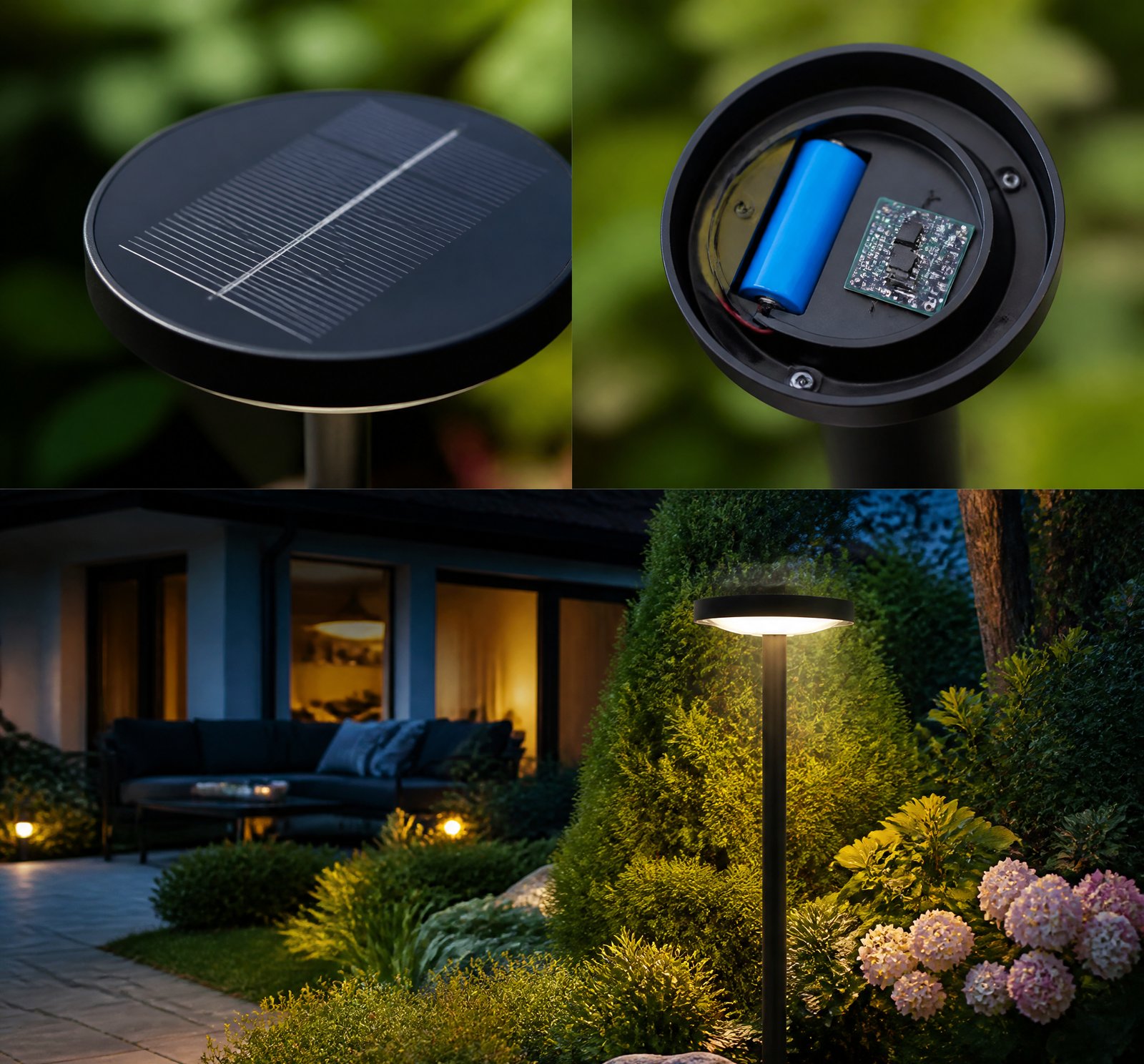
> Quick answer: Premium charge controllers extend battery life in solar lamps by regulating voltage and current, preventing overcharging and deep discharge through intelligent algorithms and real-time monitoring. They use MPPT technology to maximize energy capture, significantly improving charging efficiency [1][23].
Understanding the Key Role of Premium Charge Controllers
Imagine a world where your solar-powered streetlights or garden lamps operate with maximum efficiency and longevity. This is made possible through premium charge controllers that not only manage battery health but also optimize the overall performance of solar energy systems.
Intelligent Voltage and Current Regulation
Premium charge controllers significantly enhance battery longevity and charging efficiency by intelligently managing voltage and current levels [1][23]. These controllers continuously monitor battery conditions, ensuring that the system operates within safe parameters. By preventing overcharging and deep discharges, they maintain optimal battery health, crucial for both lead-acid and lithium-ion chemistries [18].
Advanced Charging Algorithms
One of the standout features of premium charge controllers is their use of advanced charging algorithms that include auto-equalization steps to combat sulfation in lead-acid batteries. Every 28 days or when the battery charge is low, these controllers deliver a 3-hour over-voltage charge at 14.5V, effectively reducing plate sulfation [19][24]. This process helps maintain battery integrity by preventing degradation mechanisms that can shorten lifespan.
Maximum Power Point Tracking (MPPT)
A key mechanism for enhancing charging efficiency is the use of MPPT technology. Unlike traditional PWM controllers, MPPT controllers dynamically adjust the operating voltage to match the maximum power point (VMP) of the solar panel [19][23]. This ensures peak efficiency even in low-light conditions, maximizing energy capture and transferring it efficiently to the battery system.
Protective Features: Low-Voltage Disconnect (LVD)
To prevent excessive discharge cycles that can damage batteries, premium controllers implement LVD at 11.0V. The system automatically reconnects when voltage reaches 12V again, safeguarding against deep discharge [19][24]. These protective measures directly extend battery lifespan by maintaining safe operating parameters.
Intelligent Load Management
In addition to managing charging cycles, premium charge controllers also optimize load management. They can dim lights during parts of the night or use sensors and timers to adjust output based on environmental conditions and user needs [8][10][21]. This dynamic approach reduces energy consumption and minimizes stress on the battery.
Thermal Management
Advanced thermal management is another critical feature that supports extended battery life, particularly in high-temperature environments. Real-time temperature monitoring and active cooling systems ensure batteries operate within safe ranges, reducing risks of overheating and thermal runaway [1][2][7].
Comparison Table: PWM vs MPPT Charge Controllers
| Feature | PWM Controller | MPPT Controller |
|–––––––––|–––––––––––-|––––––––––––|
| Efficiency | Less efficient in variable conditions [19][23] | More efficient, especially in low-light conditions [13][25] |
| Voltage Regulation | Limited to panel voltage | Can convert higher voltages (e.g., 30–33V) to usable energy for a 12V battery system [19] |
Key Takeaways
- Intelligent Regulation: Premium charge controllers use advanced algorithms and real-time monitoring to prevent overcharging and deep discharge, extending battery life.
- MPPT Technology: MPPT controllers dynamically adjust voltage to maximize solar panel efficiency, especially in low-light conditions.
- Protective Features: LVD and auto-equalization help maintain safe operating parameters for batteries.
Frequently Asked Questions
„`json
[
{
„q”: „How do premium charge controllers prevent overcharging?”,
„a”: „Premium charge controllers continuously monitor battery voltage to ensure it does not exceed safe levels, preventing damage from overcharging. [1][23]„
},
{
„q”: „What is the role of MPPT in solar lamps?”,
„a”: „MPPT technology maximizes energy capture by dynamically adjusting the operating voltage of solar panels to match their maximum power point (VMP), ensuring peak efficiency even in low-light conditions. [19][23]„
},
{
„q”: „How do controllers manage battery temperature?”,
„a”: „Controllers use real-time monitoring and active cooling systems to keep batteries within safe thermal ranges, reducing risks of overheating and extending lifespan. [1][2][7]„
}
]
„`
References
- [1] WO2010057138A2_-_Energy-efficient_solar-powered_outdoor_lighting__593d23e6 — patent
source passage
during peak electricity-usage hours, while also being capable of being autonomous (independent of the grid) operation in the event of disaster or other grid outage. In such embodiments, an inverter and control and measurement systems (G3 in Figure 18) will be added, for example, inside the pole, to cooperate with the utility grid and measure and record the system's energy contribution to the grid. [0082] Controllers are provided to manage charging of the batteries and delivery of energy to the lighting system and/or other components. Control of the operative connection between the batteries 62 and panel 14 and the operative connection between the batteries and the LED fixture 40 and other components may be done by electronics, circuitry, and/or semiconductors, for example, control board 80 shown in Figure 7. The controller(s) preferably continually monitor(s) battery voltage and temperature to determine battery health, to improve both battery performance and life. As further described later in this document, said controller(s) preferably control the speed and the amount that the batteries are charged and discharged, which can significantly affect battery life. Combined with the preferred cooling system for managing battery temperature, the batteries of the preferred embodiments are expected to exhibit longer lives, and better performance, than prior art batteries installed in solar-powered light systems. [0083] A first controller function delivers a low-current (trickle) char
- [2] US7731383B2_-_Solar-powered_light_pole_and_LED_light_fixture__4dec276e — patent
source passage
provide the benefit of supplementing the grid during peak electricity-usage hours, while also being capable of being autonomous (independent of the grid) in the event of disaster or other grid outage. In such embodiments, an inverter and control and measurement systems (G3 in FIG. 18 ) will be added, for example, inside the pole, to cooperate with the utility grid and measure and record the system's energy contribution to the grid. Controllers are provided to manage charging of the batteries and delivery of energy to the lighting system and/or other components. Control of the operative connection between the batteries 62 and panel 14 and the operative connection between the batteries and the LED fixture 40 and other components may be done by electronics, circuitry, and/or semiconductors, for example, control board 80 shown in FIG. 7 . The controller(s) preferably continually monitor(s) battery voltage and temperature to determine battery health, to improve both battery performance and life. Said controller(s) preferably control the speed and the amount that the batteries are charged and discharged, which can significantly affect battery life. Combined with the preferred cooling system for managing battery temperature, the batteries of the preferred embodiments are expected to exhibit longer lives, and better performance, than prior art batteries installed in solar-powered light systems. A first controller delivers a low-current (trickle) charge from the solar collector panel
- [7] US7731383B2_-_Solar-powered_light_pole_and_LED_light_fixture__4dec276e — patent
source passage
preferably also charging batteries during the day, and then receiving less expensive power from the grid during the night and/or also receiving power from the batteries as a supplemental/backup power source. – connection to the grid is shown schematically as G 1 (underground) or G 2 (above-ground) and one of skill in the art will understand how to build, install, and manage said connections. – G 1 underground – G 2 above-ground – an inverter and control and measurement systems G 3 in FIG. 18 – an inverter and control and measurement systems will be added, for example, inside the pole, to cooperate with the utility grid and measure and record the system's energy contribution to the grid. – Controllers are provided to manage charging of the batteries and delivery of energy to the lighting system and/or other components. – Control of the operative connection between the batteries 62 and panel 14 and the operative connection between the batteries and the LED fixture 40 and other components may be done by electronics, circuitry, and/or semiconductors, for example, control board 80 shown in FIG. 7 . – the controller(s) preferably continually monitor(s) battery voltage and temperature to determine battery health, to improve both battery performance and life. – Said controller(s) preferably control the speed and the amount that the batteries are charged and discharged, which can significantly affect battery life. – the batteries of the preferred embodiments are expected to exhibit lo
- [8] US20100029268A1_-_Wireless_autonomous_solar-powered_outdoor__58410db8 — patent
source passage
battery performance and life. – Said controller(s) preferably control the speed and the amount that the batteries are charged and discharged, which can significantly affect battery life. – the batteries of the preferred embodiments are expected to exhibit longer lives, and better performance, than prior art batteries installed in solar-powered light systems. – a first controller delivers a low-current (trickle) charge from the solar collector panel 14 to the batteries. This controller also preferably limits the maximum voltage to a voltage that will not damage or degrade the battery/batteries. – a second controller draws current from the battery/batteries and delivers it to the LED fixture and other electric device(s) requiring power from the batteries. The minimum battery voltage is also protected by the controller to prevent excess battery drain. – the controller(s) may dim the lights during part or all of the night to reduce the amount of energy being consumed while still providing some lighting of the surroundings. – the controller(s) may turn the light on based on a signal from a photocell and/or a motion sensor, and off with a timeclock, for example. – the controller system(s) may comprise computer logic, memory, timers, ambient light sensors, transmitters, receivers, and/or data recording and/or output means. – Said controller systems may comprise only electronics and apparatus to operate the single light 10 , 10 ′ in which it resides, or may additionally comprise elec
- [10] US20120020060A1_-_Energy-efficient_solar-powered_-_Google_Patents__619c8cff — patent
source passage
controller(s) preferably continually monitor(s) battery voltage and temperature to determine battery health, to improve both battery performance and life. As further described later in this document, said controller(s) preferably control the speed and the amount that the batteries are charged and discharged, which can significantly affect battery life. Combined with the preferred cooling system for managing battery temperature, the batteries of the preferred embodiments are expected to exhibit longer lives, and better performance, than prior art batteries installed in solar-powered light systems. – A first controller function delivers a low-current (trickle) charge from the solar collector panel 14 to the batteries. This controller also preferably limits the maximum voltage to a voltage that will not damage or degrade the battery/batteries. A second controller function draws current from the battery/batteries and delivers it to the LED fixture and other electric device(s) requiring power from the batteries. The minimum battery voltage is also protected by the controller to prevent excess battery drain. During prolonged periods of inclement weather and low daytime energy generation, the controller(s) may dim the lights during part or all of the night to reduce the amount of energy being consumed while still providing some lighting of the surroundings. The controller(s) may turn the light on based on a signal from a photocell and/or a motion sensor, and off with a timeclock, fo
- [13] CN117955218A_-_MPPT-based_solar_street_lamp_control_system__d7f0e078 — patent
source passage
lamp is improved. According to the invention, when the solar street lamp is controlled, the maximum output power of the photovoltaic solar panel is obtained through controlling the output voltage of the photovoltaic solar panel so as to improve the charging efficiency, and meanwhile, the charging coverage rate of the battery is collected so as to quantitatively analyze the charging and discharging conditions of the battery, thereby being convenient for knowing the illumination condition of the position of the solar street lamp and controlling the operation of the solar street lamp. The preferred embodiments of the invention disclosed above are intended only to assist in the explanation of the invention. The preferred embodiments are not intended to be exhaustive or to limit the invention to the precise form disclosed. Obviously, many modifications and variations are possible in light of the above teaching. The embodiments were chosen and described in order to best explain the principles of the invention and the practical application, to thereby enable others skilled in the art to best understand and utilize the invention. The invention is limited only by the claims and the full scope and equivalents thereof.
- [18] Solar_Power_World__Solar_Basics_At_Home_What_are_solar_charge_controllers__iOqJvWRyxSA — youtube
source passage
# Solar Basics (At Home!): What are solar charge controllers? Source: YouTube — Solar Power World URL: https://www.youtube.com/watch?v=iOqJvWRyxSA Video ID: iOqJvWRyxSA Transcript: generated welcome to solar basics i'm kelsey misbrenner senior editor of solar power world and i'm kelly pickerel editor-in-chief customers who want a hybrid solar plus storage system that can sell solar generated electricity during the day and store that power for use at night during an outage or during peak times we'll need a solar charge controller charge controllers are the regulators of solar plus storage systems they deliver power from the pv array to system loads and the battery bank when the battery bank is nearly full the controller will taper off the charging current to maintain the required voltage to fully charge the battery and keep it topped off by being able to regulate the voltage the solar controller protects the battery batteries can be the most expensive part of the system and a solar charge controller protects them from both overcharging and under charging extended periods with a partial state of charge will cause the plates of a lead acid battery to become sulfated and greatly reduce life expectancy lithium battery chemistries are equally vulnerable to chronic undercharging running batteries down to zero can kill them quickly overcharging all types of batteries can cause irreparable damage overcharging lead acid batteries may cause excessive gassing that can actually boil the w
- [19] WO2010057138A2_-_Energy-efficient_solar-powered_outdoor_lighting__593d23e6 — patent
source passage
and which are incorporated by reference into this document. – the battery charge controller is connected between the solar collector and the battery subsystem. – the charge controller controls the current and voltage delivered to the batteries and optimizes the charging conditions to the battery to assure that the batteries are not overcharged, preferably according to the multi-step process portrayed in Figure 40. – the multi-step process features an auto-equalize step (to 14.5V) every 28 days or if low charge, that is preferably 3 hours of over-voltage charge to reduce plate sulfation. – the charge controller provides for low voltage disconnect (LVD) at 11.0V (and reconnect when 12 V is again reached), to prevent damage to the batteries from over-draining. Battery charge is monitored through voltage level, as shown in Figure 41. – the Inventors and Applicant use an advanced Maximum Power Point Tracking technology that converts the voltage from the solar panel that is above the battery voltage into usable energy that can be stored in the batteries. Older technologies, including PWM (pulse width modulation) charge controllers, are unable to do this. Because the batteries are a 12V system and the solar panel is a 30-33V system, significant energy can be converted from the solar panel for storage in the batteries. This enables the system to generate energy on sunny days (or even mostly-sunny days) typically well in excess of what is consumed at night. This excess is stored in th
- [21] US8588830B2_-_Wireless_autonomous_solar-powered_outdoor_lighting__6d9bbfe3 — patent
source passage
of the preferred embodiments are expected to exhibit longer lives, and better performance, than prior art batteries installed in solar-powered light systems. – a first controller delivers a low-current (trickle) charge from the solar collector panel 14 to the batteries. This controller also preferably limits the maximum voltage to a voltage that will not damage or degrade the battery/batteries. – a second controller draws current from the battery/batteries and delivers it to the LED fixture and other electric device(s) requiring power from the batteries. The minimum battery voltage is also protected by the controller to prevent excess battery drain. – the controller(s) may dim the lights during part or all of the night to reduce the amount of energy being consumed while still providing some lighting of the surroundings. – the controller(s) may turn the light on based on a signal from a photocell and/or a motion sensor, and off with a timeclock, for example. – the controller system(s) may comprise computer logic, memory, timers, ambient light sensors, transmitters, receivers, and/or data recording and/or output means. – Said controller systems may comprise only electronics and apparatus to operate the single light 10 , 10 ′ in which it resides, or may additionally comprise electronics and apparatus that communicate with a central control station and/or with other street lights. – Said communication is preferably accomplished wirelessly, for example, by means of a “multiple-nod
- [23] Research_in_lithium-ion_batteries_-_Wikipedia__684ccf67 — wikipedia
source passage
the charging cycles.[104] In 2014, researchers at MIT, Sandia National Laboratories, Samsung Advanced Institute of Technology America and Lawrence Berkeley National Laboratory discovered that uniform charging could be used with increased charge speed to speed up battery charging. This discovery could also increase cycle durability to ten years. Traditionally slower charging prevented overheating, which shortens cycle durability. The researchers used a particle accelerator to learn that in conventional devices each increment of charge is absorbed by a single or a small number of particles until they are charged, then moves on. By distributing charge/discharge circuitry throughout the electrode, heating and degradation could be reduced while allowing much greater power density.[105][106] In 2014, researchers at Qnovo developed software for a smartphone and a computer chip capable of speeding up re-charge time by a factor of 3-6, while also increasing cycle durability. The technology is able to understand how the battery needs to be charged most effectively, while avoiding the formation of dendrites.[107] In 2019, Chao-Yang Wang from Penn State University found that it is possible to recharge the (conventional) lithium-ion batteries of EV's in under 10 minutes. He did so by heating the battery to 60 °C, recharging it and then cooling if quickly afterwards. This causes only very little damage to the batteries. Professor Wang used a thin nickel foil with one end attached to the ne
- [24] US20120020060A1_-_Energy-efficient_solar-powered_-_Google_Patents__619c8cff — patent
source passage
salt spray, etc. It can be easily wash with water and detergents. – Measured power generation on Inventors'/Applicant's poles according to embodiments of the invention has been measured at least 50 Watts at Boise, Id., U.S.A. during the month of November, with energy generated well in excess of 300 Watt-hours. The actual performance of the system depends on the location of the installation. Many factors influence this including shading from adjacent buildings or structures and weather patterns in the area installed. Inventors'/Applicant's preferred solar collector is currently the Unisolar PVL 136, specifications for which may be obtained from the company Unisolar and/or from appendices in the provisional U.S. application of which this application claims benefit and which are incorporated by reference into this document. – The battery charge controller is connected between the solar collector and the battery subsystem. The charge controller controls the current and voltage delivered to the batteries and optimizes the charging conditions to the battery to assure that the batteries are not overcharged, preferably according to the multi-step process portrayed in FIG. 40 . In addition to the main steps shown inFIG. 40 , the multi-step process features an auto-equalize step (to 14.5V) every 28 days or if low charge, that is preferably 3 hours of over-voltage charge to reduce plate sulfation. Also, the charge controller provides for low voltage disconnect (LVD) at 11.0V (and reconn
- [25] CN107093923A_-_High-efficiency_solar_charger_baby_-_Google_Patents__4972733d — patent
source passage
increase the area of the solar battery panel (2), which can realize charging and discharging at the same time. High-speed charging and discharging, and with multiple protection circuits, it can be used even in low-light environments, such as cloudy days. It has high charging efficiency, is economical and practical, and meets the needs of most people. Description 技术领域technical field 本发明涉及便携式电子产品技术领域,具体涉及一种高效率太阳能充电宝。The invention relates to the technical field of portable electronic products, in particular to a high-efficiency solar charging treasure. 背景技术Background technique 随着社会的进步,智能手机已经大量的普及。因为在空闲的时候每个人都会使用手机,所以电子产品的电池续航就成了很大的问题。太阳能充电宝的产生,可以在很大程度上的解决这一问题。With the progress of society, smart phones have been widely popularized. Because everyone uses their phones in their spare time, the battery life of electronic gadgets has become a big problem. The generation of solar charging treasure can solve this problem to a large extent. 现在的充电宝大多数只能使用市电充电,出门在外的时候很不方便。而且太阳能充电宝还处于刚起步的状态,技术还不够成熟,普遍存在着充放电效率低,太阳能板面积过小,没有实用价值,或者面积大不便携带,弱光环境下,例如阴天不能充电,并且有安全隐患等问题。因此,目前需要一种智能高效率的太阳能充电宝,在体积较小的同时,还能实现快速充放,阴天也能用。Most of the current charging treasures can only be charged by mains electricity, which is very inconvenient when going out. Moreover, the solar power bank is still in its infancy, and the technology is not yet mature enough. The charging and discharging efficiency is generally low, the area of the solar panel is too small, it has no practical value, or the area is too large to carry, and
during peak electricity-usage hours, while also being capable of being autonomous (independent of the grid) operation in the event of disaster or other grid outage. In such embodiments, an inverter and control and measurement systems (G3 in Figure 18) will be added, for example, inside the pole, to cooperate with the utility grid and measure and record the system's energy contribution to the grid. [0082] Controllers are provided to manage charging of the batteries and delivery of energy to the lighting system and/or other components. Control of the operative connection between the batteries 62 and panel 14 and the operative connection between the batteries and the LED fixture 40 and other components may be done by electronics, circuitry, and/or semiconductors, for example, control board 80 shown in Figure 7. The controller(s) preferably continually monitor(s) battery voltage and temperature to determine battery health, to improve both battery performance and life. As further described later in this document, said controller(s) preferably control the speed and the amount that the batteries are charged and discharged, which can significantly affect battery life. Combined with the preferred cooling system for managing battery temperature, the batteries of the preferred embodiments are expected to exhibit longer lives, and better performance, than prior art batteries installed in solar-powered light systems. [0083] A first controller function delivers a low-current (trickle) char
provide the benefit of supplementing the grid during peak electricity-usage hours, while also being capable of being autonomous (independent of the grid) in the event of disaster or other grid outage. In such embodiments, an inverter and control and measurement systems (G3 in FIG. 18 ) will be added, for example, inside the pole, to cooperate with the utility grid and measure and record the system's energy contribution to the grid. Controllers are provided to manage charging of the batteries and delivery of energy to the lighting system and/or other components. Control of the operative connection between the batteries 62 and panel 14 and the operative connection between the batteries and the LED fixture 40 and other components may be done by electronics, circuitry, and/or semiconductors, for example, control board 80 shown in FIG. 7 . The controller(s) preferably continually monitor(s) battery voltage and temperature to determine battery health, to improve both battery performance and life. Said controller(s) preferably control the speed and the amount that the batteries are charged and discharged, which can significantly affect battery life. Combined with the preferred cooling system for managing battery temperature, the batteries of the preferred embodiments are expected to exhibit longer lives, and better performance, than prior art batteries installed in solar-powered light systems. A first controller delivers a low-current (trickle) charge from the solar collector panel
preferably also charging batteries during the day, and then receiving less expensive power from the grid during the night and/or also receiving power from the batteries as a supplemental/backup power source. – connection to the grid is shown schematically as G 1 (underground) or G 2 (above-ground) and one of skill in the art will understand how to build, install, and manage said connections. – G 1 underground – G 2 above-ground – an inverter and control and measurement systems G 3 in FIG. 18 – an inverter and control and measurement systems will be added, for example, inside the pole, to cooperate with the utility grid and measure and record the system's energy contribution to the grid. – Controllers are provided to manage charging of the batteries and delivery of energy to the lighting system and/or other components. – Control of the operative connection between the batteries 62 and panel 14 and the operative connection between the batteries and the LED fixture 40 and other components may be done by electronics, circuitry, and/or semiconductors, for example, control board 80 shown in FIG. 7 . – the controller(s) preferably continually monitor(s) battery voltage and temperature to determine battery health, to improve both battery performance and life. – Said controller(s) preferably control the speed and the amount that the batteries are charged and discharged, which can significantly affect battery life. – the batteries of the preferred embodiments are expected to exhibit lo
battery performance and life. – Said controller(s) preferably control the speed and the amount that the batteries are charged and discharged, which can significantly affect battery life. – the batteries of the preferred embodiments are expected to exhibit longer lives, and better performance, than prior art batteries installed in solar-powered light systems. – a first controller delivers a low-current (trickle) charge from the solar collector panel 14 to the batteries. This controller also preferably limits the maximum voltage to a voltage that will not damage or degrade the battery/batteries. – a second controller draws current from the battery/batteries and delivers it to the LED fixture and other electric device(s) requiring power from the batteries. The minimum battery voltage is also protected by the controller to prevent excess battery drain. – the controller(s) may dim the lights during part or all of the night to reduce the amount of energy being consumed while still providing some lighting of the surroundings. – the controller(s) may turn the light on based on a signal from a photocell and/or a motion sensor, and off with a timeclock, for example. – the controller system(s) may comprise computer logic, memory, timers, ambient light sensors, transmitters, receivers, and/or data recording and/or output means. – Said controller systems may comprise only electronics and apparatus to operate the single light 10 , 10 ′ in which it resides, or may additionally comprise elec
controller(s) preferably continually monitor(s) battery voltage and temperature to determine battery health, to improve both battery performance and life. As further described later in this document, said controller(s) preferably control the speed and the amount that the batteries are charged and discharged, which can significantly affect battery life. Combined with the preferred cooling system for managing battery temperature, the batteries of the preferred embodiments are expected to exhibit longer lives, and better performance, than prior art batteries installed in solar-powered light systems. – A first controller function delivers a low-current (trickle) charge from the solar collector panel 14 to the batteries. This controller also preferably limits the maximum voltage to a voltage that will not damage or degrade the battery/batteries. A second controller function draws current from the battery/batteries and delivers it to the LED fixture and other electric device(s) requiring power from the batteries. The minimum battery voltage is also protected by the controller to prevent excess battery drain. During prolonged periods of inclement weather and low daytime energy generation, the controller(s) may dim the lights during part or all of the night to reduce the amount of energy being consumed while still providing some lighting of the surroundings. The controller(s) may turn the light on based on a signal from a photocell and/or a motion sensor, and off with a timeclock, fo
lamp is improved. According to the invention, when the solar street lamp is controlled, the maximum output power of the photovoltaic solar panel is obtained through controlling the output voltage of the photovoltaic solar panel so as to improve the charging efficiency, and meanwhile, the charging coverage rate of the battery is collected so as to quantitatively analyze the charging and discharging conditions of the battery, thereby being convenient for knowing the illumination condition of the position of the solar street lamp and controlling the operation of the solar street lamp. The preferred embodiments of the invention disclosed above are intended only to assist in the explanation of the invention. The preferred embodiments are not intended to be exhaustive or to limit the invention to the precise form disclosed. Obviously, many modifications and variations are possible in light of the above teaching. The embodiments were chosen and described in order to best explain the principles of the invention and the practical application, to thereby enable others skilled in the art to best understand and utilize the invention. The invention is limited only by the claims and the full scope and equivalents thereof.
# Solar Basics (At Home!): What are solar charge controllers? Source: YouTube — Solar Power World URL: https://www.youtube.com/watch?v=iOqJvWRyxSA Video ID: iOqJvWRyxSA Transcript: generated welcome to solar basics i'm kelsey misbrenner senior editor of solar power world and i'm kelly pickerel editor-in-chief customers who want a hybrid solar plus storage system that can sell solar generated electricity during the day and store that power for use at night during an outage or during peak times we'll need a solar charge controller charge controllers are the regulators of solar plus storage systems they deliver power from the pv array to system loads and the battery bank when the battery bank is nearly full the controller will taper off the charging current to maintain the required voltage to fully charge the battery and keep it topped off by being able to regulate the voltage the solar controller protects the battery batteries can be the most expensive part of the system and a solar charge controller protects them from both overcharging and under charging extended periods with a partial state of charge will cause the plates of a lead acid battery to become sulfated and greatly reduce life expectancy lithium battery chemistries are equally vulnerable to chronic undercharging running batteries down to zero can kill them quickly overcharging all types of batteries can cause irreparable damage overcharging lead acid batteries may cause excessive gassing that can actually boil the w
and which are incorporated by reference into this document. – the battery charge controller is connected between the solar collector and the battery subsystem. – the charge controller controls the current and voltage delivered to the batteries and optimizes the charging conditions to the battery to assure that the batteries are not overcharged, preferably according to the multi-step process portrayed in Figure 40. – the multi-step process features an auto-equalize step (to 14.5V) every 28 days or if low charge, that is preferably 3 hours of over-voltage charge to reduce plate sulfation. – the charge controller provides for low voltage disconnect (LVD) at 11.0V (and reconnect when 12 V is again reached), to prevent damage to the batteries from over-draining. Battery charge is monitored through voltage level, as shown in Figure 41. – the Inventors and Applicant use an advanced Maximum Power Point Tracking technology that converts the voltage from the solar panel that is above the battery voltage into usable energy that can be stored in the batteries. Older technologies, including PWM (pulse width modulation) charge controllers, are unable to do this. Because the batteries are a 12V system and the solar panel is a 30-33V system, significant energy can be converted from the solar panel for storage in the batteries. This enables the system to generate energy on sunny days (or even mostly-sunny days) typically well in excess of what is consumed at night. This excess is stored in th
of the preferred embodiments are expected to exhibit longer lives, and better performance, than prior art batteries installed in solar-powered light systems. – a first controller delivers a low-current (trickle) charge from the solar collector panel 14 to the batteries. This controller also preferably limits the maximum voltage to a voltage that will not damage or degrade the battery/batteries. – a second controller draws current from the battery/batteries and delivers it to the LED fixture and other electric device(s) requiring power from the batteries. The minimum battery voltage is also protected by the controller to prevent excess battery drain. – the controller(s) may dim the lights during part or all of the night to reduce the amount of energy being consumed while still providing some lighting of the surroundings. – the controller(s) may turn the light on based on a signal from a photocell and/or a motion sensor, and off with a timeclock, for example. – the controller system(s) may comprise computer logic, memory, timers, ambient light sensors, transmitters, receivers, and/or data recording and/or output means. – Said controller systems may comprise only electronics and apparatus to operate the single light 10 , 10 ′ in which it resides, or may additionally comprise electronics and apparatus that communicate with a central control station and/or with other street lights. – Said communication is preferably accomplished wirelessly, for example, by means of a “multiple-nod
the charging cycles.[104] In 2014, researchers at MIT, Sandia National Laboratories, Samsung Advanced Institute of Technology America and Lawrence Berkeley National Laboratory discovered that uniform charging could be used with increased charge speed to speed up battery charging. This discovery could also increase cycle durability to ten years. Traditionally slower charging prevented overheating, which shortens cycle durability. The researchers used a particle accelerator to learn that in conventional devices each increment of charge is absorbed by a single or a small number of particles until they are charged, then moves on. By distributing charge/discharge circuitry throughout the electrode, heating and degradation could be reduced while allowing much greater power density.[105][106] In 2014, researchers at Qnovo developed software for a smartphone and a computer chip capable of speeding up re-charge time by a factor of 3-6, while also increasing cycle durability. The technology is able to understand how the battery needs to be charged most effectively, while avoiding the formation of dendrites.[107] In 2019, Chao-Yang Wang from Penn State University found that it is possible to recharge the (conventional) lithium-ion batteries of EV's in under 10 minutes. He did so by heating the battery to 60 °C, recharging it and then cooling if quickly afterwards. This causes only very little damage to the batteries. Professor Wang used a thin nickel foil with one end attached to the ne
salt spray, etc. It can be easily wash with water and detergents. – Measured power generation on Inventors'/Applicant's poles according to embodiments of the invention has been measured at least 50 Watts at Boise, Id., U.S.A. during the month of November, with energy generated well in excess of 300 Watt-hours. The actual performance of the system depends on the location of the installation. Many factors influence this including shading from adjacent buildings or structures and weather patterns in the area installed. Inventors'/Applicant's preferred solar collector is currently the Unisolar PVL 136, specifications for which may be obtained from the company Unisolar and/or from appendices in the provisional U.S. application of which this application claims benefit and which are incorporated by reference into this document. – The battery charge controller is connected between the solar collector and the battery subsystem. The charge controller controls the current and voltage delivered to the batteries and optimizes the charging conditions to the battery to assure that the batteries are not overcharged, preferably according to the multi-step process portrayed in FIG. 40 . In addition to the main steps shown inFIG. 40 , the multi-step process features an auto-equalize step (to 14.5V) every 28 days or if low charge, that is preferably 3 hours of over-voltage charge to reduce plate sulfation. Also, the charge controller provides for low voltage disconnect (LVD) at 11.0V (and reconn
increase the area of the solar battery panel (2), which can realize charging and discharging at the same time. High-speed charging and discharging, and with multiple protection circuits, it can be used even in low-light environments, such as cloudy days. It has high charging efficiency, is economical and practical, and meets the needs of most people. Description 技术领域technical field 本发明涉及便携式电子产品技术领域,具体涉及一种高效率太阳能充电宝。The invention relates to the technical field of portable electronic products, in particular to a high-efficiency solar charging treasure. 背景技术Background technique 随着社会的进步,智能手机已经大量的普及。因为在空闲的时候每个人都会使用手机,所以电子产品的电池续航就成了很大的问题。太阳能充电宝的产生,可以在很大程度上的解决这一问题。With the progress of society, smart phones have been widely popularized. Because everyone uses their phones in their spare time, the battery life of electronic gadgets has become a big problem. The generation of solar charging treasure can solve this problem to a large extent. 现在的充电宝大多数只能使用市电充电,出门在外的时候很不方便。而且太阳能充电宝还处于刚起步的状态,技术还不够成熟,普遍存在着充放电效率低,太阳能板面积过小,没有实用价值,或者面积大不便携带,弱光环境下,例如阴天不能充电,并且有安全隐患等问题。因此,目前需要一种智能高效率的太阳能充电宝,在体积较小的同时,还能实现快速充放,阴天也能用。Most of the current charging treasures can only be charged by mains electricity, which is very inconvenient when going out. Moreover, the solar power bank is still in its infancy, and the technology is not yet mature enough. The charging and discharging efficiency is generally low, the area of the solar panel is too small, it has no practical value, or the area is too large to carry, and