
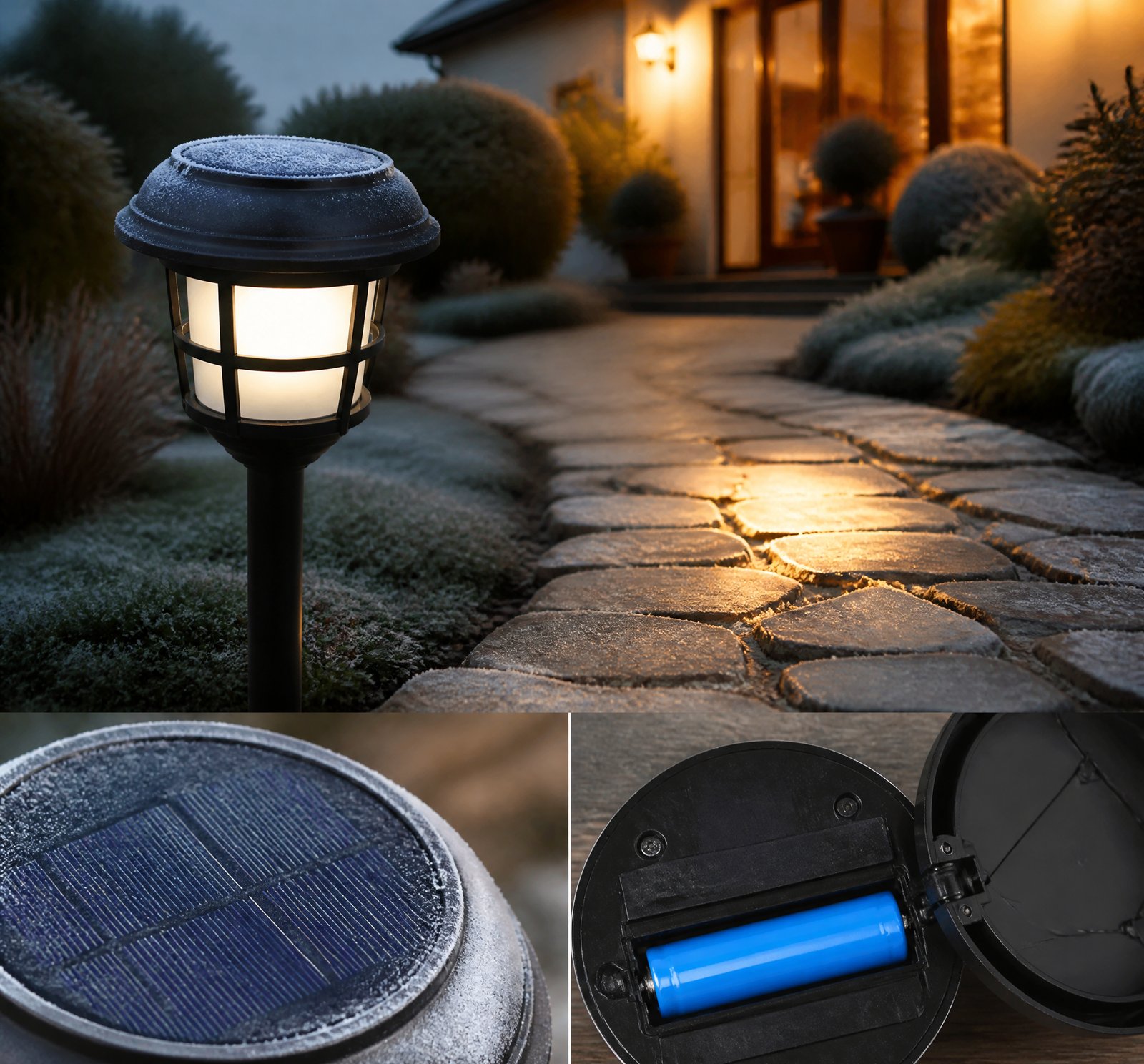
> Quick answer: Solar lamps in Romania estimate battery capacity by monitoring voltage and previous day’s solar production in Amp-Hours [5]. When energy input drops, systems dim lights or switch to lower power modes based on battery voltage, historical data, motion detection, and time of day [5][24]. This adaptive strategy ensures operation through extended cloudy periods while preserving battery health [12].
Solar lamps have become a reliable solution for outdoor lighting across Romania, even during prolonged cloudy spells. With winter months often bringing limited sunlight, these systems must intelligently manage power to avoid failure at night. The key lies in how they calculate remaining battery capacity and adjust light output dynamically.
How Solar Lamps Monitor Battery Capacity
Battery capacity is not measured directly in real time but inferred through multiple indicators. One primary method involves tracking battery voltage, which declines as energy is consumed and charge depletes [5][24]. As voltage drops, the system recognizes reduced stored energy and prepares for conservation. This voltage-based estimation is a foundational signal used across models to trigger low-power responses.
Beyond real-time voltage, systems also analyze past performance. By recording the previous day’s solar production in Amp-Hours (Ah), the lamp can assess whether charging was sufficient [5]. If today’s input is below expected levels—common during extended cloud cover—the system predicts a higher risk of nighttime failure and proactively shifts into energy-saving mode [5].
Some advanced models use a digital energy counter to track cumulative solar input during charging cycles [17], contributing to longer-term capacity forecasting. This historical data helps fine-tune dimming schedules, especially when comparing seasonal patterns such as winter vs. summer sunshine.
Decision-Making Behind Dimming and Power Reduction
The decision to dim lights or switch to lower power modes isn’t based on a single factor. Instead, it combines real-time and predictive data:
- Battery Voltage: A drop below a preset threshold triggers reduced brightness [5][24].
- Solar Production (Ah): If yesterday’s solar harvest was low, the system assumes less energy is available and reduces output [5].
- Historical Data: Some systems use one-year-old energy collection data to estimate typical winter performance and pre-emptively adjust brightness [20].
- Time of Day: Lights brighten back to full intensity about 30 minutes before dawn [5], ensuring visibility at sunrise even when batteries are low.
- Motion Detection: When motion is detected, LEDs increase brightness for a set time, then return to standby [1][4], prioritizing energy during active periods.
These inputs allow the system to balance safety, visibility, and battery longevity.
Energy Savings Modes in Action
When conditions worsen—such as multi-day cloudy weather—systems activate predefined energy-saving modes like E3, E4, and E5. In these modes:
- Light starts at 80%, 70%, or 50% of full brightness [24],
- Then gradually dims down to as low as 7.5% [24],
- The time before dawn brightening is also shortened to conserve power [24].
These modes are especially critical during winter in Romania, where solar insolation can be as low as 1–2 hours per day [8][10].
Practical Considerations for Romanian Users
While exact voltage thresholds or timing rules aren’t specified in the patents [5][24], the system design prioritizes battery longevity. Over-discharging significantly shortens battery life [12], so systems are engineered to avoid deep discharge by dimming early rather than shutting off abruptly.
This adaptive intelligence ensures reliable lighting even in the least sunny months, making solar lamps a sustainable investment across Romania’s varied climate.
Comparison of Solar Lamp Energy Management Features
| Feature | Function | Source |
|–––|–––|–––|
| Voltage Monitoring | Triggers dimming if battery level drops | [5][24] |
| Ah-Based Solar Tracking | Adjusts behavior based on prior day’s solar input | [5] |
| Digital Energy Counter | Logs total solar input for long-term forecasting | [17] |
| Motion-Activated Brightness | Increases output only when needed | [1][4] |
| Time-of-Day Scheduling | Brightens before dawn based on preset timing | [5] |
Key Takeaways
- Solar lamps in Romania use voltage and prior day’s solar production (Ah) to estimate battery capacity [5].
- Dimming is triggered by low voltage, poor solar harvest, motion detection, and time of day [5][24].
- Energy-saving modes reduce brightness dynamically and extend operation during cloudy periods [24].
- Systems use historical data to anticipate winter performance and prevent battery stress [20].
- Avoiding deep discharge preserves battery life, which is critical for long-term reliability [12].
References
- [1] WO2010057138A2_-_Energy-efficient_solar-powered_outdoor_lighting__593d23e6 — patent
source passage
so that the solar collector is generally vertical; providing a lighting fixture connected to the pole and comprising multiple light emitting diodes (LEDs); providing at least one battery operatively connected to the solar collector panel and the LEDs; providing at least one motion sensor on said pole; actively controlling energy delivery from said at least one battery to said LEDs, by turning on, dimming and turning off said LEDs according to at least one mode of operation, said at least one mode of operation comprising a normal operation mode comprising turning said LEDs on at dusk to full brightness for a first predetermined amount of time, and, after said first predetermined amount of time, dimming said LEDs to a first fraction of said full brightness, until said at least one motion sensor detects a motion event near said pole and then increasing energy delivery to said LEDs for a second predetermined amount of time starting when said at least one motion sensor no longer detects said motion event, followed by reducing energy delivery to said LEDs to dim said LEDs, so that the LEDs are dimmed to less than full brightness in between motion events. The methods may include actively controlling energy delivery from said at least one battery to said LEDs by increasing energy delivery to said LEDs for a third predetermined amount of time before dawn so that said LEDs remain at full brightness until dawn. The methods may include dimming said LEDs when said at least one battery fal
- [4] US20120020060A1_-_Energy-efficient_solar-powered_-_Google_Patents__619c8cff — patent
source passage
and comprising multiple light emitting diodes (LEDs); providing at least one battery operatively connected to the solar collector panel and the LEDs; providing at least one motion sensor on said pole; actively controlling energy delivery from said at least one battery to said LEDs, by turning on, dimming and turning off said LEDs according to at least one mode of operation, said at least one mode of operation comprising a normal operation mode comprising turning said LEDs on at dusk to full brightness for a first predetermined amount of time, and, after said first predetermined amount of time, dimming said LEDs to a first fraction of said full brightness, until said at least one motion sensor detects a motion event near said pole and then increasing energy delivery to said LEDs for a second predetermined amount of time starting when said at least one motion sensor no longer detects said motion event, followed by reducing energy delivery to said LEDs to dim said LEDs, so that the LEDs are dimmed to less than full brightness in between motion events. The methods may include actively controlling energy delivery from said at least one battery to said LEDs by increasing energy delivery to said LEDs for a third predetermined amount of time before dawn so that said LEDs remain at full brightness until dawn. The methods may include dimming said LEDs when said at least one battery falls to a battery voltage in the range of 1-2 volts above a minimum safe battery voltage, said minimum s
- [5] US20120020060A1_-_Energy-efficient_solar-powered_-_Google_Patents__619c8cff — patent
source passage
to 100% for 10 minutes after the last-detected motion. It then dims back down to the lower setting over one minute. Towards dawn, the light will brighten back up to full brightness approximately 30 minutes (factory preset) prior to dawn. When the photocell threshold for dawn is crossed, the light will turn off. – FIG. 47 portrays examples of how system conditions can be utilized to determine the appropriate energy modes based on current states to modify power delivered, to the light or other loads, beyond or instead of the “normal” changes over time shown in FIG. 46 . – the voltage of the batteries (on the right of the figure) is one indicator of how much energy is available in the battery storage. As the battery voltage drops, the energy mode is adjusted so that energy can be conserved. – the Ah decision block is referring to the solar production (in Amp-Hours, Ah) from the previous day. This Ah information is also an indicator of whether or not energy needs to be conserved. On any given day, if the energy produced is less than normal, then the energy mode is adjusted to conserve energy, over and above the adjustments shown in FIG. 46 , preferably during the following night. – Modes E1 through E6 Energy Savings Modes are available (modes E1 through E6), and selection of the modes is determined by the measuring the battery voltage at the end of the day. – modes E1 and E2 the light is still brought up to full brightness initially & then dimmed down to less than 25% brightness
- [8] WO2010057138A2_-_Energy-efficient_solar-powered_outdoor_lighting__593d23e6 — patent
source passage
to or contribution of energy from the electrical grid, without any replacement of the batteries, and without any energy input into the batterys or any part of the lighting system except from the amorphous PV cell material on each pole. [0292] In Figure 50, one may see long periods of days and weeks of sky cover (measured in hours during the day, defined as "cloudy" or "overcast" as judged from the local weather report), but the system maintained minimum battery voltage above the important benchmark of approximately 1 1 volts all through the roughly two month winter period, except for the "waving tree limb" incident in December, described above. In Figures 51 A and B, which represent a different test, of a set of poles operating over about 2.5 winter months (the graph being split roughly in two), multiple poles operating independent of each other and autonomously (not tied to the grid) all performed continuously at or above 1 1 volts throughout the winter, despite long stretches of little or no sunshine per day. Even during the dark days of January, only a few of the poles came near to dropping to 1 1 volts, at which increased dimming action per the energy-savings mode E6 kept the poles operating successfully, at least at dimmed condition, during the crucual periods after dusk and before dawn, and upon motion being sensed. Up an increase in sunshine late in January, the batteries all rebounded to a range of 12 — 12.5 volts. [0294] Preferred embodiments may therefore be describ
- [10] US20120020060A1_-_Energy-efficient_solar-powered_-_Google_Patents__619c8cff — patent
source passage
energy savings, if dimming of the light is not sufficient to protect the batteries and operability of the system. – FIG. 49 is a plot of photovoltaic cell efficiency vs. time, for many types of PV cells, wherein the preferred PV material is shown to be in the range of 12-16 percent efficiency, and typically 13%. – FIG. 50 is a plot of test data from a solar-powered pole operating without any tie to the grid, wherein the light met lighting needs through many weeks of sky cover (clouds, overcast) in a safe range for the batteries. – FIGS. 51A and B are a plot (split onto two sheets) of operation of six solar-powered poles, without any tie to the grid, operating according to an embodiment of the active control system, wherein the poles successfully met lighting needs through many weeks of low sunshine days, even through January, when the light poles met said lighting needs by being dimmed according to energy-savings modes described later in this document. – Referring to the Figures, there may be seen some, but not the only, embodiments of the invention. FIGS. 1-18 portray some, but not the only, embodiments of solar-powered light poles and lights that may form a “population” of poles for arrays and networks and/or be implemented as single or multiple, non-networked lighting poles.FIGS. 19-33E schematically portray some, but not the only, embodiments of arrays of outdoor lighting and other powered devices that are preferably managed as embodiments of the invented wireless intelli
- [12] EP2954381B1_-_System_and_method_for_enhanced_security_for_solar__fa161e85 — patent
source passage
order to facilitate a long operational life, the battery may be substantially over dimensioned to avoid deep discharges. This is because deep discharges strongly limit the battery life. For example, Fig. 2 shows a graph of a degradation curve of battery energy storage. – In such solar powered lighting systems, the energy collection, however, is weather dependent. This means that the daily energy collection may not be enough to cover a (lighting) load for one night. – The over dimensioned battery may also constitute an energy buffer to bridge one or more days of bad weather when there is not enough sunlight to collect energy for normal operation. During one or more bad days, the solar lighting system may deplete part or the entire energy buffer at night. When there were several days of bad weather, however, the energy stored in the battery may not be enough to cover the complete night. – The conventional lighting systems discussed above may also include a dimming override feature. In certain situations, such as for example a traffic accident or emergency condition, an external signal is sent to a lighting unit to override a set dimming level. The external signal may be used to set a dimmed light level to full brightness and revert to an original dimming light level when the situation is deemed to have ended. An automatic reset may also be used to restore the original dimming light level. In the automatic reset case, a predetermined time interval (e.g., a few hours) is generall
- [17] US20110252678A1_-_Method_apparatus_and_system_-_Google_Patents__66ffc305 — patent
source passage
near optimum amount of electric power which can be supplied from the battery to the LEDs such that the LEDs operate at a relatively constant level of LED light output brightness all during the upcoming night time hours. – According to another aspect, the disclosure includes the use of a control circuit which provides a relatively constant level of LED light output brightness all during the night time hours. The control circuit accomplishes this by recording the amount of solar energy provided to the battery during the previous daytime hours, and then calculates the optimum amount of energy that the battery can then provide to the LEDs during all the upcoming night time hours. The control circuit automatically repeats this process each 24 hour period. The LEDs are thereby always illuminating the translucent street name sign faces during the night time hours, regardless how little or how much solar energy was provided to the battery during the previous daytime charging cycle. – According to another aspect of the disclosure, the control circuit includes a circuit mounted on a printed circuit board (PCB) and generally includes a variety of digital and analog circuit components. The control circuit records the amount of solar energy provided from sunlight provided from the solar panels for battery charging. This is accomplished with a digital energy counter that records the solar energy charge to the battery each time interval (typically one second is used) and totalizes the resul
- [20] US20120020060A1_-_Energy-efficient_solar-powered_-_Google_Patents__619c8cff — patent
source passage
photovoltaic material having an efficiency in bright sunshine in the range of 10-16%. 20. A method as in claim 15 , further comprising determining an amount to dim said luminaire, during a nighttime when said at least one motion sensor is not sensing motion near the pole, based on a method comprising measuring battery voltage of said at least one battery at dusk prior to said nighttime. 21. A method as in claim 15 , further comprising determining an amount to dim said luminaire, during a nighttime when said at least one motion sensor is not sensing motion near the pole, based on a method comprising measuring and recording energy production in amp-hours by said solar collector panel in a previous time period comprising one or more days. 22. A method as in claim 15 , further comprising determining an amount to dim said luminaire, during a nighttime when said at least one motion sensor is not sensing motion near the pole, based on a method comprising measuring and recording historical data of energy collection by the solar collector panel over a period one year earlier. 23. A method as in claim 15 , wherein said first fraction is 25% or less of full brightness. 24. A method as in claim 15 , wherein a plurality of batteries are provided and the method further comprises disconnected selected batteries of said plurality of batteries when said selected batteries fail. 25. A method as in claim 15 , further comprising not raising brightness of said luminaire in response to motion dete
- [24] WO2010057138A2_-_Energy-efficient_solar-powered_outdoor_lighting__593d23e6 — patent
source passage
loads, beyond or instead of the "normal" changes over time shown in Figure 46. For example, the voltage of the batteries (on the right of the figure) is one indicator of how much energy is available in the battery storage. As the battery voltage drops, the energy mode is adjusted so that energy can be conserved. On the left of the figure, the Ah decision block is referring to the solar production (in Amp-Hours, Ah) from the previous day. This Ah information is also an indicator of whether or not energy needs to be conserved. On any given day, if the energy produced is less than normal, then the energy mode is adjusted to conserve energy, over and above the adjustments shown in Figure 46, preferably during the following night. [0232] Energy Savings Modes are available (modes El through E6), and selection of the modes is determined by the measuring the battery voltage at the end of the day. During modes El and E2 the light is still brought up to full brightness initially & then dimmed down to less than 25% brightness down to a minimum brightness (for example, of 5 – 10%). During modes E3 through E5, the light is brought up to 80%, 70% and 50% of full brightness initially, and then dimmed down to less than 25% brightness down to as low as 7.5%. The time at which the light is brightened back up before dawn in also scaled back so that it is not up at full brightness for as long as normal mode. If the battery voltage drops below a minimum level (Vnb < 1 IV), the controller enters t
so that the solar collector is generally vertical; providing a lighting fixture connected to the pole and comprising multiple light emitting diodes (LEDs); providing at least one battery operatively connected to the solar collector panel and the LEDs; providing at least one motion sensor on said pole; actively controlling energy delivery from said at least one battery to said LEDs, by turning on, dimming and turning off said LEDs according to at least one mode of operation, said at least one mode of operation comprising a normal operation mode comprising turning said LEDs on at dusk to full brightness for a first predetermined amount of time, and, after said first predetermined amount of time, dimming said LEDs to a first fraction of said full brightness, until said at least one motion sensor detects a motion event near said pole and then increasing energy delivery to said LEDs for a second predetermined amount of time starting when said at least one motion sensor no longer detects said motion event, followed by reducing energy delivery to said LEDs to dim said LEDs, so that the LEDs are dimmed to less than full brightness in between motion events. The methods may include actively controlling energy delivery from said at least one battery to said LEDs by increasing energy delivery to said LEDs for a third predetermined amount of time before dawn so that said LEDs remain at full brightness until dawn. The methods may include dimming said LEDs when said at least one battery fal
and comprising multiple light emitting diodes (LEDs); providing at least one battery operatively connected to the solar collector panel and the LEDs; providing at least one motion sensor on said pole; actively controlling energy delivery from said at least one battery to said LEDs, by turning on, dimming and turning off said LEDs according to at least one mode of operation, said at least one mode of operation comprising a normal operation mode comprising turning said LEDs on at dusk to full brightness for a first predetermined amount of time, and, after said first predetermined amount of time, dimming said LEDs to a first fraction of said full brightness, until said at least one motion sensor detects a motion event near said pole and then increasing energy delivery to said LEDs for a second predetermined amount of time starting when said at least one motion sensor no longer detects said motion event, followed by reducing energy delivery to said LEDs to dim said LEDs, so that the LEDs are dimmed to less than full brightness in between motion events. The methods may include actively controlling energy delivery from said at least one battery to said LEDs by increasing energy delivery to said LEDs for a third predetermined amount of time before dawn so that said LEDs remain at full brightness until dawn. The methods may include dimming said LEDs when said at least one battery falls to a battery voltage in the range of 1-2 volts above a minimum safe battery voltage, said minimum s
to 100% for 10 minutes after the last-detected motion. It then dims back down to the lower setting over one minute. Towards dawn, the light will brighten back up to full brightness approximately 30 minutes (factory preset) prior to dawn. When the photocell threshold for dawn is crossed, the light will turn off. – FIG. 47 portrays examples of how system conditions can be utilized to determine the appropriate energy modes based on current states to modify power delivered, to the light or other loads, beyond or instead of the “normal” changes over time shown in FIG. 46 . – the voltage of the batteries (on the right of the figure) is one indicator of how much energy is available in the battery storage. As the battery voltage drops, the energy mode is adjusted so that energy can be conserved. – the Ah decision block is referring to the solar production (in Amp-Hours, Ah) from the previous day. This Ah information is also an indicator of whether or not energy needs to be conserved. On any given day, if the energy produced is less than normal, then the energy mode is adjusted to conserve energy, over and above the adjustments shown in FIG. 46 , preferably during the following night. – Modes E1 through E6 Energy Savings Modes are available (modes E1 through E6), and selection of the modes is determined by the measuring the battery voltage at the end of the day. – modes E1 and E2 the light is still brought up to full brightness initially & then dimmed down to less than 25% brightness
to or contribution of energy from the electrical grid, without any replacement of the batteries, and without any energy input into the batterys or any part of the lighting system except from the amorphous PV cell material on each pole. [0292] In Figure 50, one may see long periods of days and weeks of sky cover (measured in hours during the day, defined as "cloudy" or "overcast" as judged from the local weather report), but the system maintained minimum battery voltage above the important benchmark of approximately 1 1 volts all through the roughly two month winter period, except for the "waving tree limb" incident in December, described above. In Figures 51 A and B, which represent a different test, of a set of poles operating over about 2.5 winter months (the graph being split roughly in two), multiple poles operating independent of each other and autonomously (not tied to the grid) all performed continuously at or above 1 1 volts throughout the winter, despite long stretches of little or no sunshine per day. Even during the dark days of January, only a few of the poles came near to dropping to 1 1 volts, at which increased dimming action per the energy-savings mode E6 kept the poles operating successfully, at least at dimmed condition, during the crucual periods after dusk and before dawn, and upon motion being sensed. Up an increase in sunshine late in January, the batteries all rebounded to a range of 12 — 12.5 volts. [0294] Preferred embodiments may therefore be describ
energy savings, if dimming of the light is not sufficient to protect the batteries and operability of the system. – FIG. 49 is a plot of photovoltaic cell efficiency vs. time, for many types of PV cells, wherein the preferred PV material is shown to be in the range of 12-16 percent efficiency, and typically 13%. – FIG. 50 is a plot of test data from a solar-powered pole operating without any tie to the grid, wherein the light met lighting needs through many weeks of sky cover (clouds, overcast) in a safe range for the batteries. – FIGS. 51A and B are a plot (split onto two sheets) of operation of six solar-powered poles, without any tie to the grid, operating according to an embodiment of the active control system, wherein the poles successfully met lighting needs through many weeks of low sunshine days, even through January, when the light poles met said lighting needs by being dimmed according to energy-savings modes described later in this document. – Referring to the Figures, there may be seen some, but not the only, embodiments of the invention. FIGS. 1-18 portray some, but not the only, embodiments of solar-powered light poles and lights that may form a “population” of poles for arrays and networks and/or be implemented as single or multiple, non-networked lighting poles.FIGS. 19-33E schematically portray some, but not the only, embodiments of arrays of outdoor lighting and other powered devices that are preferably managed as embodiments of the invented wireless intelli
order to facilitate a long operational life, the battery may be substantially over dimensioned to avoid deep discharges. This is because deep discharges strongly limit the battery life. For example, Fig. 2 shows a graph of a degradation curve of battery energy storage. – In such solar powered lighting systems, the energy collection, however, is weather dependent. This means that the daily energy collection may not be enough to cover a (lighting) load for one night. – The over dimensioned battery may also constitute an energy buffer to bridge one or more days of bad weather when there is not enough sunlight to collect energy for normal operation. During one or more bad days, the solar lighting system may deplete part or the entire energy buffer at night. When there were several days of bad weather, however, the energy stored in the battery may not be enough to cover the complete night. – The conventional lighting systems discussed above may also include a dimming override feature. In certain situations, such as for example a traffic accident or emergency condition, an external signal is sent to a lighting unit to override a set dimming level. The external signal may be used to set a dimmed light level to full brightness and revert to an original dimming light level when the situation is deemed to have ended. An automatic reset may also be used to restore the original dimming light level. In the automatic reset case, a predetermined time interval (e.g., a few hours) is generall
near optimum amount of electric power which can be supplied from the battery to the LEDs such that the LEDs operate at a relatively constant level of LED light output brightness all during the upcoming night time hours. – According to another aspect, the disclosure includes the use of a control circuit which provides a relatively constant level of LED light output brightness all during the night time hours. The control circuit accomplishes this by recording the amount of solar energy provided to the battery during the previous daytime hours, and then calculates the optimum amount of energy that the battery can then provide to the LEDs during all the upcoming night time hours. The control circuit automatically repeats this process each 24 hour period. The LEDs are thereby always illuminating the translucent street name sign faces during the night time hours, regardless how little or how much solar energy was provided to the battery during the previous daytime charging cycle. – According to another aspect of the disclosure, the control circuit includes a circuit mounted on a printed circuit board (PCB) and generally includes a variety of digital and analog circuit components. The control circuit records the amount of solar energy provided from sunlight provided from the solar panels for battery charging. This is accomplished with a digital energy counter that records the solar energy charge to the battery each time interval (typically one second is used) and totalizes the resul
photovoltaic material having an efficiency in bright sunshine in the range of 10-16%. 20. A method as in claim 15 , further comprising determining an amount to dim said luminaire, during a nighttime when said at least one motion sensor is not sensing motion near the pole, based on a method comprising measuring battery voltage of said at least one battery at dusk prior to said nighttime. 21. A method as in claim 15 , further comprising determining an amount to dim said luminaire, during a nighttime when said at least one motion sensor is not sensing motion near the pole, based on a method comprising measuring and recording energy production in amp-hours by said solar collector panel in a previous time period comprising one or more days. 22. A method as in claim 15 , further comprising determining an amount to dim said luminaire, during a nighttime when said at least one motion sensor is not sensing motion near the pole, based on a method comprising measuring and recording historical data of energy collection by the solar collector panel over a period one year earlier. 23. A method as in claim 15 , wherein said first fraction is 25% or less of full brightness. 24. A method as in claim 15 , wherein a plurality of batteries are provided and the method further comprises disconnected selected batteries of said plurality of batteries when said selected batteries fail. 25. A method as in claim 15 , further comprising not raising brightness of said luminaire in response to motion dete
loads, beyond or instead of the "normal" changes over time shown in Figure 46. For example, the voltage of the batteries (on the right of the figure) is one indicator of how much energy is available in the battery storage. As the battery voltage drops, the energy mode is adjusted so that energy can be conserved. On the left of the figure, the Ah decision block is referring to the solar production (in Amp-Hours, Ah) from the previous day. This Ah information is also an indicator of whether or not energy needs to be conserved. On any given day, if the energy produced is less than normal, then the energy mode is adjusted to conserve energy, over and above the adjustments shown in Figure 46, preferably during the following night. [0232] Energy Savings Modes are available (modes El through E6), and selection of the modes is determined by the measuring the battery voltage at the end of the day. During modes El and E2 the light is still brought up to full brightness initially & then dimmed down to less than 25% brightness down to a minimum brightness (for example, of 5 – 10%). During modes E3 through E5, the light is brought up to 80%, 70% and 50% of full brightness initially, and then dimmed down to less than 25% brightness down to as low as 7.5%. The time at which the light is brightened back up before dawn in also scaled back so that it is not up at full brightness for as long as normal mode. If the battery voltage drops below a minimum level (Vnb < 1 IV), the controller enters t