
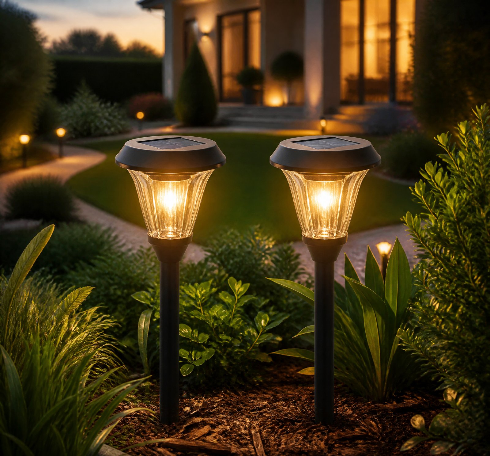
> Quick answer: The choice of optical diffuser or reflector in a 2000-lumen, wide-beam outdoor solar lamp significantly alters glare, light uniformity, and coverage area through geometric design and material properties. Prismatic and high-haze diffusers enhance uniformity and reduce glare but may decrease efficiency [1][5].
Choosing the right optical component for your 2000-lumen outdoor solar lamp can dramatically change how the light is distributed, affecting glare, uniformity, and coverage area. Below, we explore the differences between clear lenses, frosted diffusers, and prismatic reflectors to help you understand which option best suits your needs.
How Glare Is Reduced
Glare is primarily minimized by manipulating the geometry of light emission and spatial distribution through reflective and diffusive surfaces [2][8]. Anti-glare reflector cups ensure that outgoing light angles are controlled, preventing high-angle emissions that cause discomfort [8][13]. The „black light” effect can make the emitting surface appear black from certain angles, effectively hiding the source while still lighting up an area [4].
Light Uniformity Through Optical Components
Light uniformity is enhanced through reflective and refractive elements. Reflectors with shapes that intersect a plane perpendicular to the central axis improve output uniformity [4]. Prismatic or lenticular optical films can redirect light in controlled ways, increasing beam angles by up to 10% for haze ratings of 88% [5][15][18].
| Optical Component | Effect on Uniformity |
|––––––-|–––––––-|
| Clear Lens | Lower uniformity |
| Frosted Diffuser | Higher uniformity |
| Prismatic Reflector | Balanced uniformity and efficiency |
Effective Coverage Area
Coverage area is influenced by beam angle and light distribution. A wider beam angle increases the illuminated area but may reduce peak intensity [18]. Reflectors with prismatic films can broaden the beam while maintaining high output efficiency [5][15].
Clear Lens vs Frosted Diffuser vs Prismatic Reflector
- Clear Lens: Preserves light intensity but may increase glare due to direct exposure of the source [9].
- Frosted Diffuser: Reduces glare and improves uniformity by diffusing the point source, though it may absorb or scatter some light [18].
- Prismatic Reflector: Redirects light efficiently while broadening the beam angle [5][15].
Energy Efficiency in Solar Lamps
LED lamps are valued for their high efficiency, but optical components like reflectors and diffusers can enhance system efficiency by directing light where it is needed [2][8][13]. Higher haze ratings improve uniformity but may reduce overall efficiency.
Advanced Optical Design Techniques
The „black light” effect demonstrates sophisticated optical engineering to make the source invisible while still delivering light, which can effectively eliminate perceived glare without diffusing light [4].
Key Takeaways
- Glare Reduction: Anti-glare reflectors and prismatic designs control high-angle emissions.
- Uniformity Improvement: Frosted and prismatic films enhance uniformity through diffusion and redirection.
- Coverage Area: Wider beam angles increase coverage but may decrease peak intensity.
Frequently Asked Questions
[{
„q”: „How does a frosted diffuser reduce glare?”,
„a”: „A frosted diffuser reduces glare by scattering light, which diffuses the point source and improves uniformity [18].”
},
{
„q”: „What is the ‘black light’ effect?”,
„a”: „The ‘black light’ effect makes the emitting surface appear black from certain angles, effectively hiding the lamp while still lighting up an area [4].”
},
{
„q”: „How do prismatic films enhance efficiency?”,
„a”: „Prismatic films redirect light with high efficiency and broaden the beam angle, enhancing output performance [5][15].”
}]
References
- [1] US7172307B2_-_Solar_powered_garden_light_-_Google_Patents__499b74da — patent
source passage
accessory 22 may modulate (e.g., focus) light rays emanating from the lights 14 . – a light diffuser 24 ( FIG. 1 ) may be placed over the refractor/reflector 18 , through which pass light rays reflected from the refractor/reflector 18 . – the light diffuser 24 is generally spherical and may be transparent or translucent (or anything between). Diffuser 24 may have any size, shape and color. – the garden light 10 may be sealed against liquids, such as rain, and other environmental factors. – a sealing element 26 such as a rubber grommet, may be placed at the junction of the refractor/reflector 18 and the optical accessory 22 to seal the refractor/reflector 18 with respect to the rest of the assembly against passage of liquid therethrough. – the garden light assembly may be supported on a mounting pole 28 , which may be attached to the assembly with a cup-shaped adapter 30 ( FIG. 1 ). – the garden light assembly may be supported on other fixtures, such as but not limited to, wall-mounted fixtures, low-profile mounts and many others. – External components of the garden light assembly may be constructed of any suitable material, such as but not limited to, metal (e.g., stainless steel, aluminum or others) or plastic (e.g., polycarbonate or other plastics). Landscapes – Life Sciences & Earth Sciences (AREA) – Sustainable Development (AREA) – Engineering & Computer Science (AREA) – General Engineering & Computer Science (AREA) – Non-Portable Lighting Devices Or Systems Thereof (AREA
- [2] EP3957905A1_-_Anti-glare_lamp_and_lighting_-_Google_Patents__c16f78f8 — patent
source passage
September 16, 2020 – The invention relates to the field of lighting technology, in particular to an anti-glare lamp and a lighting arrangement method using the lamp. The complete disclosure and content of is introduced by reference into this document. Especially the definition of the angles with respect to the reflector and the LED are introduced.EP 21167248.0 – In the context of energy conservation and environmental protection, LED lamps are increasingly used in the home and commercial lighting fields because of their high light-emitting efficiency and good light-gathering performance. Regarding indoor lighting design applications in homes, offices or commercial places, visual comfort is extremely important. To achieve this, products that reduce direct glare and reflected glare should be selected. The correct placement of the lamp and the use of optical components that can reduce direct glare and reflected glare can reduce the impact of glare on people or damage to human eyes. – To reduce glare, it is necessary to provide a uniform direct beam as much as possible, and reduce the horizontal beam parallel to the horizontal plane of the lighting space. For this reason, the existing space lighting mainly uses reflectors or shutters to restrict the illumination beam to the undesired direction, or increase the shading angle of the lamp (that is, the angle between the illumination beam and the horizontal line). Another method is to use a scattering element to cover the bright light
- [4] EP3957905A1_-_Anti-glare_lamp_and_lighting_-_Google_Patents__c16f78f8 — patent
source passage
which can not only meet the lighting needs, but will not give people a dazzling feeling, creating a very comfortable lighting effect. – the black light lighting effect is that when people look at the light-emitting surface of the lamp from a certain angle, the light-emitting surface is black, and no light from the lamp can be seen. It feels that the lamp does not light up, which brings an excellent lighting experience. The problem of dazzling and heavy glare is solved. – the reflector 300 will also distribute light of the second light beam 202, and its shape can be circular or polygonal. – the reflector 300 In order to improve the uniformity of light output, in a plane perpendicular to the central axis 400, the reflector 300 intersects the plane to form a regular polygon. – the regular polygon may be a triangle, rectangle, pentagon, etc. – the reflector 300 In a plane perpendicular to the central axis 400, the reflector 300 intersects the plane to form a rectangle or a regular hexagon. Rectangles are easier to achieve multiple arrangements, and hexagons are also a better choice, which can form a honeycomb arrangement. – the inner surface of the reflector 300 is composed of two opposing reflective structures 301, and the reflective structures 301 are at least partially straight or curved. – the center of curvature is located outside the reflector 300. – the light source 200 adopts a light-emitting chip, has a certain volume, and the light-emitting surface has an area. Taking t
- [5] WO2013112329A1_-_Light_reflector_cone_-_Google_Patents__fe35d034 — patent
source passage
or high efficiency diffuse reflection surfaces: – a light source such as a compact fluorescent lamp (CFL) – CFL compact fluorescent lamp – the beam angle can be adjusted without changing the shape of the reflector. – FIG 2B-1 An example embodiment of a reflector is shown in FIG 2B-1, wherein a lenticular optical film (2500) and reflection film (2400) form a hollow cone-shaped light reflector. – the lenticular optical film (2500) may comprise a prismatic optical film such as BEF II film manufactured by 3M, which includes rows of triangular prisms with 90-degree apexes. – a prismatic film such as BEF II manufactured by 3M may be utilized, and should not be construed to limit the scope of use of other types of lenticular or holographic optical films. – Prismatic lenticular optical film may have the advantage of lower cost, due to its widespread use and demand, as well as excellent optical performance in example embodiments. – orientation of the prism rows on lenticular optical film utilized and described herein in certain example embodiments may have an effect on the reflection and refraction properties of the example light reflector embodiment, which will be described in further detail below. – terminology and frame of reference for the orientation of the prism rows will now be provided. – a piece of optical film may be configured, cut, and subsequently formed into a portion of a hollow cone shape. – the cone shape 2500 may include an apex 2970, and the surface of cone shape 25
- [8] EP3957904A1_-_An_anti-glare_reflector_cup_and_a_lamp_with_the__e8f32e38 — patent
source passage
axis is a maximum straight outgoing light angle, and the maximum included angle between the second light beam which is reflected by the reflective sidewall and emitted from the light exit end and the optical axis is the maximum reflection outgoing light angle, and the maximum reflection outgoing light angle is less than or equal to the maximum straight outgoing light angle. The invention provides excellent lighting experience and solves the problems of glare. Description – This application claims priority to Chinese Patent Application No. .CN 202010828951.3, filed on August 18, 2020 – The invention relates to the technical field of lighting, in particular to an anti-glare reflector cup and a lamp with the anti-glare reflector cup. – In the context of energy conservation and environmental protection, LED lamps are increasingly used in the home and commercial lighting fields because of their high light-emitting efficiency and good light-gathering performance. – Regarding indoor lighting design applications in homes, offices or commercial places, visual comfort is extremely important. To achieve this, products that reduce direct glare and reflected glare should be selected. The correct placement of the lamp and the use of optical components that can reduce direct glare and reflected glare can reduce the impact of glare on people or damage to human eyes. – To reduce glare, it is necessary to provide a uniform direct beam as much as possible, and reduce the horizontal beam paralle
- [9] LED_Lighting_in_Museums_and_Art_Galleries_Technical_-_Canadaca__7f9b6307 — authority
source passage
to case buffering, RH dropped only 2%. Why do LED lamps produce more glare? Exhibit designers have commented that LEDs produce more problems of glare than the lamps they replace. Each of the individual white LEDs (white cylinders in Figure 8) is a very small and very intense patch of light, but so was the filament of a tungsten or halogen lamp (white bar in Figure 8). Even the less intense surface of a fluorescent lamp will be a source of glare if it is in the viewer’s line of sight, and therein lies the problem. Figure 8 illustrates the role of geometry in determining whether a lamp in a fixture causes glare. In traditional reflector lamps, the filament was recessed well behind the front of the lamp. Many directional LED lamps are designed with the LEDs at the front surface of the lamp, with no reflector at the sides and no diffuser layer. Even if the old track fittings have snoots, their anti-glare geometry assumes that the source is close to the back of the snoot, not out near the front. The control of glare from any light source has always been about the control of geometry (that is, the line of sight between viewer and source), as shown by the red and yellow lines in Figure 8. LED lamps not only are more likely to expose their point sources to the viewer (red lines), they also have many more points per lamp, hence a stronger feeling of visual noise. Reducing glare by lamp selection Some directional LED lamps were designed with glare control in mind, and we can expect fut
- [13] US20220057070A1_-_Anti-Glare_Reflector_Cup_and_a_Lamp_with__54cb8c1b — patent
source passage
light angle, and the maximum reflection outgoing light angle is less than or equal to the maximum straight outgoing light angle. The reflective cup provides excellent lighting experience and solves the problems of glare. Description – This application claims priority to a Chinese Patent Application No. CN 202010828951.3, filed on Aug. 18, 2020. – The invention relates to the technical field of lighting, in particular to an anti-glare reflector cup and a lamp with the anti-glare reflector cup. – In the context of energy conservation and environmental protection, LED lamps are increasingly used in the home and commercial lighting fields because of their high light-emitting efficiency and good light-gathering performance. – Regarding indoor lighting design applications in homes, offices or commercial places, visual comfort is extremely important. To achieve this, products that reduce direct glare and reflected glare should be selected. The correct placement of the lamp and the use of optical components that can reduce direct glare and reflected glare can reduce the impact of glare on people or damage to human eyes. – To reduce glare, it is necessary to provide a uniform direct beam as much as possible, and reduce the horizontal beam parallel to the horizontal plane of the lighting space. For this reason, the existing space lighting mainly uses reflectors or shutters to restrict the illumination beam to the undesired direction, or increase the shading angle of the lamp (that is,
- [15] CA2855729A1_-_Light_reflector_cone_-_Google_Patents__59910ead — patent
source passage
light source may comprise a compact fluorescent lamp, an incandescent lamp, or an LED lamp etc. An example embodiment of reflector as described may enhance the light output efficiency of the light source by reflecting, diffracting, and/or redirecting light towards the larger opening of the cone reflector assembly. The reflective and refractive properties of flat prismatic optical film are well documented and understood to those skilled in the arts, from both the perspectives of light incident on the structured surface, and light incident on the smooth surface, and will not be discussed here in detail. When prism film and a rear reflection surface as previously described are formed into a cone and a light source is disposed inside the cone, analysis of the propagation of reflected and refracted light within the cone may become exponentially more complex when compared to a flat surface. Factors which may cause this increased complexity may be understood with respect to the following: FIG 13A represents a not-to-scale drawing of two prism rows 13400 of a prism film configured into a cone shape, that are relatively vertical, and with the structured surface facing the inside of the cone. The axis of the base of each prism row, as shown by line X, may not be parallel to each other, such that the angle A may be less than 90 degrees. FIG 13B depicts the situation when the prism row 13400 (only a single prism row is shown here for clarity) is aligned relatively horizontally, with the
- [18] US8534881B2_-_Light_reflector_cone_-_Google_Patents__09692e34 — patent
source passage
affect the light distribution pattern. Generally, the higher the haze rating, the broader the light dispersion pattern from the reflector may be, and the lower the efficiency may be. For example, on a compact fluorescent lamp, a haze rating of 50% may broaden the beam angle by about 5% compared to no top diffusion film, and a diffusion film with a haze rating of 88% may broaden the beam angle by about 10%. Accordingly, the haze rating of the diffusion film may be tailored to somewhat broaden light distribution requirements of the reflector. FIG. 2D shows a cross sectional view of an example embodiment of reflector cone (not to scale), which includes the rear reflector 2400, the lenticular optical film 2500 with structured surface 2510 facing the inner portion of the cone 2120, and top diffusion film 2600 with structured surface facing the inner portion of the cone 2120. In an example embodiment of the light reflector, as shown in FIG. 2D and described above may have the advantage of having a somewhat increased beam angle, which may be advantageous for applications requiring a broader light distribution pattern. The diffusion film 2600 may also serve to protect the delicate structured surface of the lenticular optical film 2510 from scratches, dust and abrasions. Some diffusion films may allow for periodic cleaning without being damaged. More importantly, the diffusion film may function to give a more pleasing visual appearance to the reflector, especially when the lamp is off
accessory 22 may modulate (e.g., focus) light rays emanating from the lights 14 . – a light diffuser 24 ( FIG. 1 ) may be placed over the refractor/reflector 18 , through which pass light rays reflected from the refractor/reflector 18 . – the light diffuser 24 is generally spherical and may be transparent or translucent (or anything between). Diffuser 24 may have any size, shape and color. – the garden light 10 may be sealed against liquids, such as rain, and other environmental factors. – a sealing element 26 such as a rubber grommet, may be placed at the junction of the refractor/reflector 18 and the optical accessory 22 to seal the refractor/reflector 18 with respect to the rest of the assembly against passage of liquid therethrough. – the garden light assembly may be supported on a mounting pole 28 , which may be attached to the assembly with a cup-shaped adapter 30 ( FIG. 1 ). – the garden light assembly may be supported on other fixtures, such as but not limited to, wall-mounted fixtures, low-profile mounts and many others. – External components of the garden light assembly may be constructed of any suitable material, such as but not limited to, metal (e.g., stainless steel, aluminum or others) or plastic (e.g., polycarbonate or other plastics). Landscapes – Life Sciences & Earth Sciences (AREA) – Sustainable Development (AREA) – Engineering & Computer Science (AREA) – General Engineering & Computer Science (AREA) – Non-Portable Lighting Devices Or Systems Thereof (AREA
September 16, 2020 – The invention relates to the field of lighting technology, in particular to an anti-glare lamp and a lighting arrangement method using the lamp. The complete disclosure and content of is introduced by reference into this document. Especially the definition of the angles with respect to the reflector and the LED are introduced.EP 21167248.0 – In the context of energy conservation and environmental protection, LED lamps are increasingly used in the home and commercial lighting fields because of their high light-emitting efficiency and good light-gathering performance. Regarding indoor lighting design applications in homes, offices or commercial places, visual comfort is extremely important. To achieve this, products that reduce direct glare and reflected glare should be selected. The correct placement of the lamp and the use of optical components that can reduce direct glare and reflected glare can reduce the impact of glare on people or damage to human eyes. – To reduce glare, it is necessary to provide a uniform direct beam as much as possible, and reduce the horizontal beam parallel to the horizontal plane of the lighting space. For this reason, the existing space lighting mainly uses reflectors or shutters to restrict the illumination beam to the undesired direction, or increase the shading angle of the lamp (that is, the angle between the illumination beam and the horizontal line). Another method is to use a scattering element to cover the bright light
which can not only meet the lighting needs, but will not give people a dazzling feeling, creating a very comfortable lighting effect. – the black light lighting effect is that when people look at the light-emitting surface of the lamp from a certain angle, the light-emitting surface is black, and no light from the lamp can be seen. It feels that the lamp does not light up, which brings an excellent lighting experience. The problem of dazzling and heavy glare is solved. – the reflector 300 will also distribute light of the second light beam 202, and its shape can be circular or polygonal. – the reflector 300 In order to improve the uniformity of light output, in a plane perpendicular to the central axis 400, the reflector 300 intersects the plane to form a regular polygon. – the regular polygon may be a triangle, rectangle, pentagon, etc. – the reflector 300 In a plane perpendicular to the central axis 400, the reflector 300 intersects the plane to form a rectangle or a regular hexagon. Rectangles are easier to achieve multiple arrangements, and hexagons are also a better choice, which can form a honeycomb arrangement. – the inner surface of the reflector 300 is composed of two opposing reflective structures 301, and the reflective structures 301 are at least partially straight or curved. – the center of curvature is located outside the reflector 300. – the light source 200 adopts a light-emitting chip, has a certain volume, and the light-emitting surface has an area. Taking t
or high efficiency diffuse reflection surfaces: – a light source such as a compact fluorescent lamp (CFL) – CFL compact fluorescent lamp – the beam angle can be adjusted without changing the shape of the reflector. – FIG 2B-1 An example embodiment of a reflector is shown in FIG 2B-1, wherein a lenticular optical film (2500) and reflection film (2400) form a hollow cone-shaped light reflector. – the lenticular optical film (2500) may comprise a prismatic optical film such as BEF II film manufactured by 3M, which includes rows of triangular prisms with 90-degree apexes. – a prismatic film such as BEF II manufactured by 3M may be utilized, and should not be construed to limit the scope of use of other types of lenticular or holographic optical films. – Prismatic lenticular optical film may have the advantage of lower cost, due to its widespread use and demand, as well as excellent optical performance in example embodiments. – orientation of the prism rows on lenticular optical film utilized and described herein in certain example embodiments may have an effect on the reflection and refraction properties of the example light reflector embodiment, which will be described in further detail below. – terminology and frame of reference for the orientation of the prism rows will now be provided. – a piece of optical film may be configured, cut, and subsequently formed into a portion of a hollow cone shape. – the cone shape 2500 may include an apex 2970, and the surface of cone shape 25
axis is a maximum straight outgoing light angle, and the maximum included angle between the second light beam which is reflected by the reflective sidewall and emitted from the light exit end and the optical axis is the maximum reflection outgoing light angle, and the maximum reflection outgoing light angle is less than or equal to the maximum straight outgoing light angle. The invention provides excellent lighting experience and solves the problems of glare. Description – This application claims priority to Chinese Patent Application No. .CN 202010828951.3, filed on August 18, 2020 – The invention relates to the technical field of lighting, in particular to an anti-glare reflector cup and a lamp with the anti-glare reflector cup. – In the context of energy conservation and environmental protection, LED lamps are increasingly used in the home and commercial lighting fields because of their high light-emitting efficiency and good light-gathering performance. – Regarding indoor lighting design applications in homes, offices or commercial places, visual comfort is extremely important. To achieve this, products that reduce direct glare and reflected glare should be selected. The correct placement of the lamp and the use of optical components that can reduce direct glare and reflected glare can reduce the impact of glare on people or damage to human eyes. – To reduce glare, it is necessary to provide a uniform direct beam as much as possible, and reduce the horizontal beam paralle
to case buffering, RH dropped only 2%. Why do LED lamps produce more glare? Exhibit designers have commented that LEDs produce more problems of glare than the lamps they replace. Each of the individual white LEDs (white cylinders in Figure 8) is a very small and very intense patch of light, but so was the filament of a tungsten or halogen lamp (white bar in Figure 8). Even the less intense surface of a fluorescent lamp will be a source of glare if it is in the viewer’s line of sight, and therein lies the problem. Figure 8 illustrates the role of geometry in determining whether a lamp in a fixture causes glare. In traditional reflector lamps, the filament was recessed well behind the front of the lamp. Many directional LED lamps are designed with the LEDs at the front surface of the lamp, with no reflector at the sides and no diffuser layer. Even if the old track fittings have snoots, their anti-glare geometry assumes that the source is close to the back of the snoot, not out near the front. The control of glare from any light source has always been about the control of geometry (that is, the line of sight between viewer and source), as shown by the red and yellow lines in Figure 8. LED lamps not only are more likely to expose their point sources to the viewer (red lines), they also have many more points per lamp, hence a stronger feeling of visual noise. Reducing glare by lamp selection Some directional LED lamps were designed with glare control in mind, and we can expect fut
light angle, and the maximum reflection outgoing light angle is less than or equal to the maximum straight outgoing light angle. The reflective cup provides excellent lighting experience and solves the problems of glare. Description – This application claims priority to a Chinese Patent Application No. CN 202010828951.3, filed on Aug. 18, 2020. – The invention relates to the technical field of lighting, in particular to an anti-glare reflector cup and a lamp with the anti-glare reflector cup. – In the context of energy conservation and environmental protection, LED lamps are increasingly used in the home and commercial lighting fields because of their high light-emitting efficiency and good light-gathering performance. – Regarding indoor lighting design applications in homes, offices or commercial places, visual comfort is extremely important. To achieve this, products that reduce direct glare and reflected glare should be selected. The correct placement of the lamp and the use of optical components that can reduce direct glare and reflected glare can reduce the impact of glare on people or damage to human eyes. – To reduce glare, it is necessary to provide a uniform direct beam as much as possible, and reduce the horizontal beam parallel to the horizontal plane of the lighting space. For this reason, the existing space lighting mainly uses reflectors or shutters to restrict the illumination beam to the undesired direction, or increase the shading angle of the lamp (that is,
light source may comprise a compact fluorescent lamp, an incandescent lamp, or an LED lamp etc. An example embodiment of reflector as described may enhance the light output efficiency of the light source by reflecting, diffracting, and/or redirecting light towards the larger opening of the cone reflector assembly. The reflective and refractive properties of flat prismatic optical film are well documented and understood to those skilled in the arts, from both the perspectives of light incident on the structured surface, and light incident on the smooth surface, and will not be discussed here in detail. When prism film and a rear reflection surface as previously described are formed into a cone and a light source is disposed inside the cone, analysis of the propagation of reflected and refracted light within the cone may become exponentially more complex when compared to a flat surface. Factors which may cause this increased complexity may be understood with respect to the following: FIG 13A represents a not-to-scale drawing of two prism rows 13400 of a prism film configured into a cone shape, that are relatively vertical, and with the structured surface facing the inside of the cone. The axis of the base of each prism row, as shown by line X, may not be parallel to each other, such that the angle A may be less than 90 degrees. FIG 13B depicts the situation when the prism row 13400 (only a single prism row is shown here for clarity) is aligned relatively horizontally, with the
affect the light distribution pattern. Generally, the higher the haze rating, the broader the light dispersion pattern from the reflector may be, and the lower the efficiency may be. For example, on a compact fluorescent lamp, a haze rating of 50% may broaden the beam angle by about 5% compared to no top diffusion film, and a diffusion film with a haze rating of 88% may broaden the beam angle by about 10%. Accordingly, the haze rating of the diffusion film may be tailored to somewhat broaden light distribution requirements of the reflector. FIG. 2D shows a cross sectional view of an example embodiment of reflector cone (not to scale), which includes the rear reflector 2400, the lenticular optical film 2500 with structured surface 2510 facing the inner portion of the cone 2120, and top diffusion film 2600 with structured surface facing the inner portion of the cone 2120. In an example embodiment of the light reflector, as shown in FIG. 2D and described above may have the advantage of having a somewhat increased beam angle, which may be advantageous for applications requiring a broader light distribution pattern. The diffusion film 2600 may also serve to protect the delicate structured surface of the lenticular optical film 2510 from scratches, dust and abrasions. Some diffusion films may allow for periodic cleaning without being damaged. More importantly, the diffusion film may function to give a more pleasing visual appearance to the reflector, especially when the lamp is off