
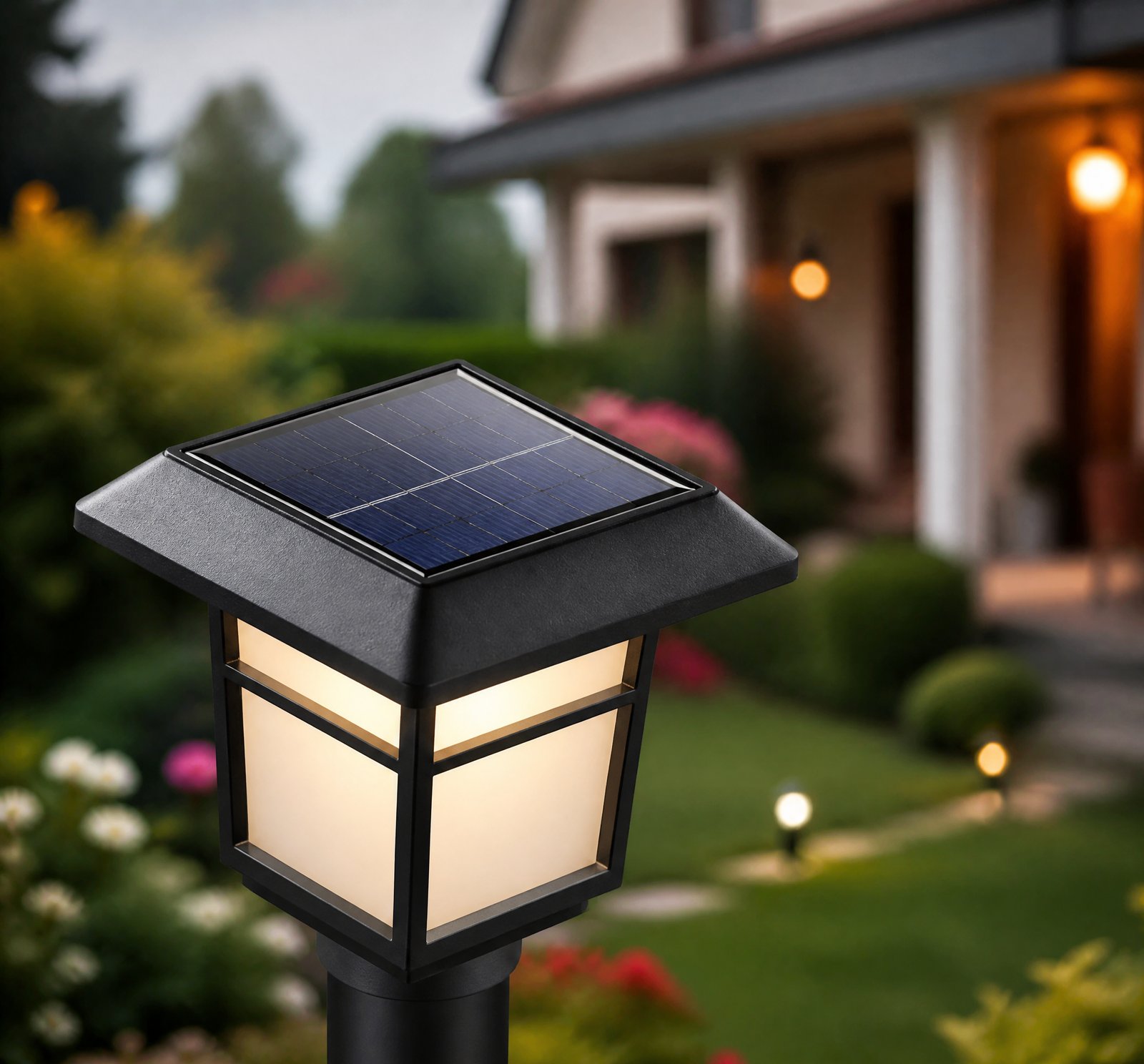
> Quick answer: Solar lamps use a charge controller to manage simultaneous charging and discharging, protecting batteries from overcharge or overdischarge [1][3]. Controllers ensure efficient power flow during daylight and night, extending battery life through smart charge cycles [1].
Solar lamps are designed with sophisticated systems that handle both charging and discharging efficiently, ensuring optimal performance. This capability is crucial for maintaining battery health and maximizing the lifespan of solar-powered lighting solutions in Romania.
How Does a Charge Controller Work?
A charge controller regulates power flow between the solar panel, battery, and load (usually an LED), preventing overcharging or overdischarging [1][3]. It ensures that the battery charges during daylight hours and powers the lamp at night. In some systems, like portable solar chargers, the controller can manage input from both solar panels and external power outlets simultaneously, facilitating dual charging sources [24].
Impact on Battery Cycle Life
The impact of simultaneous charging and discharging on battery cycle life is not explicitly addressed in the research excerpts. However, controllers play a critical role in extending battery life by preventing overcharge and overdischarge conditions [1][3]. One patent describes a controller that protects against damage from extreme weather conditions and improper charge states [1].
Battery Types and Protection Circuits
Different types of batteries are used in solar lamps, including gel electrolyte technology for high performance under deep discharging and extreme temperatures [1], lead-acid, nickel metal hydride, nickel cadmium, and lithium-ion [1]. Lithium-ion batteries, in particular, often come with protection circuits to prevent damage during charging and discharging processes [3][6].
Dual-Battery Systems
Some solar lamps use dual-battery systems to reduce the number of charge-discharge cycles on any one battery. This system charges one battery during the day while the other powers the load at night, allowing for a full charge cycle without continuous discharge [19]. While this approach decouples charging and discharging, it does not enable simultaneous operation but effectively extends overall battery life.
MPPT Technology
The Maximum Power Point Tracking (MPPT) technology optimizes energy harvesting under varying light conditions, improving charging efficiency [11][21]. This ensures effective charging even in low-light environments, reducing the need for frequent discharges and potentially extending cycle wear.
Role of User Behavior
User behavior plays a crucial role in managing battery life. Automated systems like those with motion sensors or smart controllers can reduce unnecessary energy use and cycling by activating only when needed [18][19]. In contrast, manual activation may lead to inconsistent charging patterns and more frequent or deep discharges.
Minimizing Battery Cycling
The research suggests that reducing the number of charge-discharge cycles—through intelligent design like dual-battery systems or backup batteries—can significantly extend battery lifespan, even if it means underutilizing the battery’s full capacity [4][9][19].
Key Takeaways
- Charge controllers manage simultaneous charging and discharging to protect solar lamp batteries.
- Dual-battery setups can reduce charge-discharge cycles and extend battery life.
- MPPT technology optimizes energy harvesting, improving overall efficiency.
References
- [1] Solar_lamp_-_Wikipedia__3c516988 — wikipedia
source passage
could cause problems.[6] A battery is usually housed within a metal or plastic case. Inside the case are electrodes including cathodes and anodes where chemical reactions occur. A separator also exists between cathode and anode which stops the electrodes reacting together at the same time as allowing electrical charge to flow freely between the two. Lastly, the collector conducts a charge from the battery to outside.[7] Batteries inside solar lamps usually use gel electrolyte technology with high performance in deep discharging, in order to enable use in extreme ranges of temperature.[citation needed] It may also use lead-acid, nickel metal hydride, nickel cadmium, or lithium. This part of the lamp saves up energy from the solar panel and provides power when needed at night when there is no light energy available. In general, the efficiency of photovoltaic energy conversion is limited for physical reasons. Around 24% of solar radiation of a long wavelength is not absorbed. 33% is heat lost to surroundings, and further losses are of approximately 15-20%. Only 23% is absorbed, which means a battery is a crucial part of solar lamp.[8] This section controls the entire working systems to protect battery charge. It ensures, under any circumstances including extreme weather conditions with large temperature difference, the battery does not overcharge or over discharge and damage the battery even further.[citation needed] This section also includes additional parts such as light cont
- [3] DIY_Solar_Bottle_Lamp_Details_HackadayioZom-B-Gone_HackadayioProject_O__e0a0db8b — reddit
source passage
attached in the files section. Image credit: – believe.earth How the Solar Lamp Works: The solar panel receives sunlight from the sun and converts it into electrical energy. The controller board charges the battery during the daytime and drives the LED during the nighttime. The solar lamp can be considered as a standalone Solar Photo Voltaic (SPV) system and contains four basic components: 1. Solar Panel: Convert Solar Energy to Electrical Energy 2. Controller: Charge the Battery ( Charger ) and drive the Load ( Driver ) 3. Battery: Store the Electrical Energy 4. Load (LED): Provide the desired light output How the Circuit Works? The entire circuit is broadly dived into 3 parts: 1. Charger Circuit 2. Battery Protection Circuit 3. LED Driver Circuit The power generated by the Solar Panel is extracted by the charger circuit and charges the battery. The protection circuit is responsible for providing various protections to the Li-Ion Battery. The LED driver circuit is responsible for driving the LED. Charger Circuit: The charger circuit charges the battery by taking power generated from the solar panel. It is based on a lithium-ion battery charger IC LP4060. It is a complete constant-current/constant-voltage linear charger for a single-cell lithium-ion battery. It uses only a few external components like resistors and capacitors. The circuit is based on the application circuit given in the datasheet. Battery Protection Circuit : The Battery Protection Circuit provides various pr
- [4] US10563827B2_-_Solar_powered_illumination_system_-_Google_Patents__f82b6692 — patent
source passage
decrease in a number of charging/discharging cycles of the rechargeable battery, which in turn results in longer battery and charge controller lifetime. – the illumination system further has reduced maintenance cost primarily due to the longer lifetime. Landscapes – Engineering & Computer Science (AREA) – General Engineering & Computer Science (AREA) – Life Sciences & Earth Sciences (AREA) – Sustainable Development (AREA) – Power Engineering (AREA) – Non-Portable Lighting Devices Or Systems Thereof (AREA) – Secondary Cells (AREA) Abstract The illumination system includes at least one solar panel, a charge controller, a rechargeable battery, an illumination unit connected to the battery through the controller, and a base frame supporting the solar panel and illumination unit at a top portion thereof, with the battery provided in a bottom portion of the base frame. Description The embodiments herein generally relate to an illumination system and particularly relates to a solar based illumination system with low power usage, standard optical flux and enhanced lifetime. The embodiments herein more particularly relate to an illumination system adapted to work with both solar panels and a main power supply during an off-grid and an on-grid installation respectively. Solar panels are frequently used to recharge batteries during the day that then subsequently are able to power lights at night. Solar panels may serve multiple functions, and, although it is very common for a solar pane
- [6] DIY_Solar_Bottle_Lamp_-_Hackadayio__ac29783a — reddit
source passage
Journal. It is attached in the files section. Image credit: – believe.earth How the Solar Lamp Works: The solar panel receives sunlight from the sun and converts it into electrical energy. The controller board charges the battery during the daytime and drives the LED during the nighttime. The solar lamp can be considered as a standalone Solar Photo Voltaic (SPV) system and contains four basic components: 1. Solar Panel: Convert Solar Energy to Electrical Energy 2. Controller: Charge the Battery ( Charger ) and drive the Load ( Driver ) 3. Battery: Store the Electrical Energy 4. Load (LED): Provide the desired light output How the Circuit Works? The entire circuit is broadly dived into 3 parts: 1. Charger Circuit 2. Battery Protection Circuit 3. LED Driver Circuit The power generated by the Solar Panel is extracted by the charger circuit and charges the battery. The protection circuit is responsible for providing various protections to the Li-Ion Battery. The LED driver circuit is responsible for driving the LED. Charger Circuit: The charger circuit charges the battery by taking power generated from the solar panel. It is based on a lithium-ion battery charger IC LP4060. It is a complete constant-current/constant-voltage linear charger for a single-cell lithium-ion battery. It uses only a few external components like resistors and capacitors. The circuit is based on the application circuit given in the datasheet. Battery Protection Circuit : The Battery Protection Circuit prov
- [9] SolarReviews__What_Can_A_Solar_Battery_Do_For_You__v8erkofcGRw — youtube
source passage
# What Can A Solar Battery Do For You? Source: YouTube — SolarReviews URL: https://www.youtube.com/watch?v=v8erkofcGRw Video ID: v8erkofcGRw Transcript: manual There are a couple different use cases for battery systems the first one is what we call battery backup these are systems that are designed for resilience they're designed to power loads in the house when the utility is not available in the case of hurricanes wildfires utility brown outs there's a whole bunch of reasons the utility might not be available and these battery backup systems provide energy to the loads when the utility is not there in battery backup systems the batteries remain fully charged and they're just sitting there waiting for the power to go out the nice thing about that is the batteries don't cycle often so we can use a large percentage of the capacity of the battery without having a big impact on how long that battery is going to live the downside is since they sit there kind of unused they are going to be limited in life span based on the type of battery that you're using in the system there's another type of use case for batteries and we call these advanced use cases and this is quite a bit different than a battery backup system in these use cases we're going to regularly cycle the battery and that might be once a day or even a couple of times a day one reason we would use these in situations where customers have a time of use rate structure in a time of use rate structure the amount that the cu
- [11] CN117955218A_-_MPPT-based_solar_street_lamp_control_system__d7f0e078 — patent
source passage
lamp is improved. According to the invention, when the solar street lamp is controlled, the maximum output power of the photovoltaic solar panel is obtained through controlling the output voltage of the photovoltaic solar panel so as to improve the charging efficiency, and meanwhile, the charging coverage rate of the battery is collected so as to quantitatively analyze the charging and discharging conditions of the battery, thereby being convenient for knowing the illumination condition of the position of the solar street lamp and controlling the operation of the solar street lamp. The preferred embodiments of the invention disclosed above are intended only to assist in the explanation of the invention. The preferred embodiments are not intended to be exhaustive or to limit the invention to the precise form disclosed. Obviously, many modifications and variations are possible in light of the above teaching. The embodiments were chosen and described in order to best explain the principles of the invention and the practical application, to thereby enable others skilled in the art to best understand and utilize the invention. The invention is limited only by the claims and the full scope and equivalents thereof.
- [18] WO2010057138A2_-_Energy-efficient_solar-powered_outdoor_lighting__593d23e6 — patent
source passage
so that the solar collector is generally vertical; providing a lighting fixture connected to the pole and comprising multiple light emitting diodes (LEDs); providing at least one battery operatively connected to the solar collector panel and the LEDs; providing at least one motion sensor on said pole; actively controlling energy delivery from said at least one battery to said LEDs, by turning on, dimming and turning off said LEDs according to at least one mode of operation, said at least one mode of operation comprising a normal operation mode comprising turning said LEDs on at dusk to full brightness for a first predetermined amount of time, and, after said first predetermined amount of time, dimming said LEDs to a first fraction of said full brightness, until said at least one motion sensor detects a motion event near said pole and then increasing energy delivery to said LEDs for a second predetermined amount of time starting when said at least one motion sensor no longer detects said motion event, followed by reducing energy delivery to said LEDs to dim said LEDs, so that the LEDs are dimmed to less than full brightness in between motion events. The methods may include actively controlling energy delivery from said at least one battery to said LEDs by increasing energy delivery to said LEDs for a third predetermined amount of time before dawn so that said LEDs remain at full brightness until dawn. The methods may include dimming said LEDs when said at least one battery fal
- [19] US9920895B2_-_Street_light_-_Google_Patents__b32f25f2 — patent
source passage
the generators are not being driven to generate sufficient power to illuminate the lamp. – the illumination control circuit to turn the lamp on/off may be replaced with a light sensor for switching on the lamp when the ambient light is low and switching off the lamp when the ambient light is bright. – the lights may be provided with a motion sensor for detecting the presence of vehicles/people in the vicinity of the light and the control circuits may be adapted to increase the brightness of the lamps on detection of movement and to decrease the brightness of the lamps on detection of no movement. – the street lights may be connected to other street lights in a network, the network of street lights being controllable either individually or in parallel from a Central Management System. – the network connection may be wired or wireless, and is typically by radio frequency, the control circuits of each light being provided with a transmitter and receiver. – a solar panel is provided, we adapt the acronym SHERS to S&SHERS, i.e. Solar and Small-Hours-Energy-Replacement-System. – SHERS Solar and Small-Hours-Energy-Replacement-System. – the battery or sets of batteries may be duplicated. This enables one battery to be charged as much as possible during one day from the solar panel. The other battery having been previously fully charged is then used during the night following the one day. The one battery is then fully charged following solar charging during the night's low tariff peri
- [21] CN117955218A_-_MPPT-based_solar_street_lamp_control_system__d7f0e078 — patent
source passage
unit can detect the residual life and the maximum capacity of the energy storage battery, and sends detection results of the battery life and the maximum capacity to the central control unit, the battery detection unit accumulates the service time and the charging and discharging coefficient of the battery, the battery detection unit obtains the residual life of the battery through the product of the service time of the battery and the charging and discharging coefficient as battery consumption time and the difference value of the preset life of the battery and the battery consumption time, predicts the service life of the battery in the solar street lamp, and is convenient for management personnel to maintain and prepare the battery in the street lamp in advance; the step of the battery detection unit obtaining the charge and discharge coefficient is as follows: s1: the battery detection unit acquires the current electric quantity of the battery when each charging is started, and records the difference value of the electric quantity of the battery and the battery as a charging quantity when each charging is ended; S2: the battery detection unit acquires the current electric quantity of the battery when each discharge starts, acquires the current electric quantity of the battery when each discharge ends, and records the difference value of the electric quantity of the battery twice as the discharge quantity; s3: the battery detection unit records the charge amount as K, the d
- [24] US20210376652A1_-_Portable_solar_battery_charging_-_Google__8cb6918d — patent
source passage
the housing, and charge control circuitry electrically coupled to the at least one solar panel and the battery. – the charge control circuitry includes first input circuitry for charging the battery from the at least one solar panel, and second input circuitry for charging the battery from a power outlet of the multiple power outlets. – the charge control circuitry is configured to control the first input circuitry and the second input circuitry to charge the battery using the at least one solar panel and the power outlet simultaneously. In some embodiments, the charge control circuitry is configured to control power flow from the at least one solar panel to the battery based on one or more predetermined characteristics of the at least one solar panel. In some embodiments, the quick charge controller is configured to control power flow from the solar panel for the charging station to the multiple power outlets based on power point tracking of the solar panel for the charging station. – the quick charge controller is coupled to the back of the solar panel for the charging station, for moving the charging station as a single, portable unit. – the quick charge controller includes monitoring circuitry configured to monitor illumination of the solar panel for the charging station; and communication circuitry configured to present information to a user to facilitate positioning the solar panel for the charging station based on the illumination. – the quick charge controller include
could cause problems.[6] A battery is usually housed within a metal or plastic case. Inside the case are electrodes including cathodes and anodes where chemical reactions occur. A separator also exists between cathode and anode which stops the electrodes reacting together at the same time as allowing electrical charge to flow freely between the two. Lastly, the collector conducts a charge from the battery to outside.[7] Batteries inside solar lamps usually use gel electrolyte technology with high performance in deep discharging, in order to enable use in extreme ranges of temperature.[citation needed] It may also use lead-acid, nickel metal hydride, nickel cadmium, or lithium. This part of the lamp saves up energy from the solar panel and provides power when needed at night when there is no light energy available. In general, the efficiency of photovoltaic energy conversion is limited for physical reasons. Around 24% of solar radiation of a long wavelength is not absorbed. 33% is heat lost to surroundings, and further losses are of approximately 15-20%. Only 23% is absorbed, which means a battery is a crucial part of solar lamp.[8] This section controls the entire working systems to protect battery charge. It ensures, under any circumstances including extreme weather conditions with large temperature difference, the battery does not overcharge or over discharge and damage the battery even further.[citation needed] This section also includes additional parts such as light cont
attached in the files section. Image credit: – believe.earth How the Solar Lamp Works: The solar panel receives sunlight from the sun and converts it into electrical energy. The controller board charges the battery during the daytime and drives the LED during the nighttime. The solar lamp can be considered as a standalone Solar Photo Voltaic (SPV) system and contains four basic components: 1. Solar Panel: Convert Solar Energy to Electrical Energy 2. Controller: Charge the Battery ( Charger ) and drive the Load ( Driver ) 3. Battery: Store the Electrical Energy 4. Load (LED): Provide the desired light output How the Circuit Works? The entire circuit is broadly dived into 3 parts: 1. Charger Circuit 2. Battery Protection Circuit 3. LED Driver Circuit The power generated by the Solar Panel is extracted by the charger circuit and charges the battery. The protection circuit is responsible for providing various protections to the Li-Ion Battery. The LED driver circuit is responsible for driving the LED. Charger Circuit: The charger circuit charges the battery by taking power generated from the solar panel. It is based on a lithium-ion battery charger IC LP4060. It is a complete constant-current/constant-voltage linear charger for a single-cell lithium-ion battery. It uses only a few external components like resistors and capacitors. The circuit is based on the application circuit given in the datasheet. Battery Protection Circuit : The Battery Protection Circuit provides various pr
decrease in a number of charging/discharging cycles of the rechargeable battery, which in turn results in longer battery and charge controller lifetime. – the illumination system further has reduced maintenance cost primarily due to the longer lifetime. Landscapes – Engineering & Computer Science (AREA) – General Engineering & Computer Science (AREA) – Life Sciences & Earth Sciences (AREA) – Sustainable Development (AREA) – Power Engineering (AREA) – Non-Portable Lighting Devices Or Systems Thereof (AREA) – Secondary Cells (AREA) Abstract The illumination system includes at least one solar panel, a charge controller, a rechargeable battery, an illumination unit connected to the battery through the controller, and a base frame supporting the solar panel and illumination unit at a top portion thereof, with the battery provided in a bottom portion of the base frame. Description The embodiments herein generally relate to an illumination system and particularly relates to a solar based illumination system with low power usage, standard optical flux and enhanced lifetime. The embodiments herein more particularly relate to an illumination system adapted to work with both solar panels and a main power supply during an off-grid and an on-grid installation respectively. Solar panels are frequently used to recharge batteries during the day that then subsequently are able to power lights at night. Solar panels may serve multiple functions, and, although it is very common for a solar pane
Journal. It is attached in the files section. Image credit: – believe.earth How the Solar Lamp Works: The solar panel receives sunlight from the sun and converts it into electrical energy. The controller board charges the battery during the daytime and drives the LED during the nighttime. The solar lamp can be considered as a standalone Solar Photo Voltaic (SPV) system and contains four basic components: 1. Solar Panel: Convert Solar Energy to Electrical Energy 2. Controller: Charge the Battery ( Charger ) and drive the Load ( Driver ) 3. Battery: Store the Electrical Energy 4. Load (LED): Provide the desired light output How the Circuit Works? The entire circuit is broadly dived into 3 parts: 1. Charger Circuit 2. Battery Protection Circuit 3. LED Driver Circuit The power generated by the Solar Panel is extracted by the charger circuit and charges the battery. The protection circuit is responsible for providing various protections to the Li-Ion Battery. The LED driver circuit is responsible for driving the LED. Charger Circuit: The charger circuit charges the battery by taking power generated from the solar panel. It is based on a lithium-ion battery charger IC LP4060. It is a complete constant-current/constant-voltage linear charger for a single-cell lithium-ion battery. It uses only a few external components like resistors and capacitors. The circuit is based on the application circuit given in the datasheet. Battery Protection Circuit : The Battery Protection Circuit prov
# What Can A Solar Battery Do For You? Source: YouTube — SolarReviews URL: https://www.youtube.com/watch?v=v8erkofcGRw Video ID: v8erkofcGRw Transcript: manual There are a couple different use cases for battery systems the first one is what we call battery backup these are systems that are designed for resilience they're designed to power loads in the house when the utility is not available in the case of hurricanes wildfires utility brown outs there's a whole bunch of reasons the utility might not be available and these battery backup systems provide energy to the loads when the utility is not there in battery backup systems the batteries remain fully charged and they're just sitting there waiting for the power to go out the nice thing about that is the batteries don't cycle often so we can use a large percentage of the capacity of the battery without having a big impact on how long that battery is going to live the downside is since they sit there kind of unused they are going to be limited in life span based on the type of battery that you're using in the system there's another type of use case for batteries and we call these advanced use cases and this is quite a bit different than a battery backup system in these use cases we're going to regularly cycle the battery and that might be once a day or even a couple of times a day one reason we would use these in situations where customers have a time of use rate structure in a time of use rate structure the amount that the cu
lamp is improved. According to the invention, when the solar street lamp is controlled, the maximum output power of the photovoltaic solar panel is obtained through controlling the output voltage of the photovoltaic solar panel so as to improve the charging efficiency, and meanwhile, the charging coverage rate of the battery is collected so as to quantitatively analyze the charging and discharging conditions of the battery, thereby being convenient for knowing the illumination condition of the position of the solar street lamp and controlling the operation of the solar street lamp. The preferred embodiments of the invention disclosed above are intended only to assist in the explanation of the invention. The preferred embodiments are not intended to be exhaustive or to limit the invention to the precise form disclosed. Obviously, many modifications and variations are possible in light of the above teaching. The embodiments were chosen and described in order to best explain the principles of the invention and the practical application, to thereby enable others skilled in the art to best understand and utilize the invention. The invention is limited only by the claims and the full scope and equivalents thereof.
so that the solar collector is generally vertical; providing a lighting fixture connected to the pole and comprising multiple light emitting diodes (LEDs); providing at least one battery operatively connected to the solar collector panel and the LEDs; providing at least one motion sensor on said pole; actively controlling energy delivery from said at least one battery to said LEDs, by turning on, dimming and turning off said LEDs according to at least one mode of operation, said at least one mode of operation comprising a normal operation mode comprising turning said LEDs on at dusk to full brightness for a first predetermined amount of time, and, after said first predetermined amount of time, dimming said LEDs to a first fraction of said full brightness, until said at least one motion sensor detects a motion event near said pole and then increasing energy delivery to said LEDs for a second predetermined amount of time starting when said at least one motion sensor no longer detects said motion event, followed by reducing energy delivery to said LEDs to dim said LEDs, so that the LEDs are dimmed to less than full brightness in between motion events. The methods may include actively controlling energy delivery from said at least one battery to said LEDs by increasing energy delivery to said LEDs for a third predetermined amount of time before dawn so that said LEDs remain at full brightness until dawn. The methods may include dimming said LEDs when said at least one battery fal
the generators are not being driven to generate sufficient power to illuminate the lamp. – the illumination control circuit to turn the lamp on/off may be replaced with a light sensor for switching on the lamp when the ambient light is low and switching off the lamp when the ambient light is bright. – the lights may be provided with a motion sensor for detecting the presence of vehicles/people in the vicinity of the light and the control circuits may be adapted to increase the brightness of the lamps on detection of movement and to decrease the brightness of the lamps on detection of no movement. – the street lights may be connected to other street lights in a network, the network of street lights being controllable either individually or in parallel from a Central Management System. – the network connection may be wired or wireless, and is typically by radio frequency, the control circuits of each light being provided with a transmitter and receiver. – a solar panel is provided, we adapt the acronym SHERS to S&SHERS, i.e. Solar and Small-Hours-Energy-Replacement-System. – SHERS Solar and Small-Hours-Energy-Replacement-System. – the battery or sets of batteries may be duplicated. This enables one battery to be charged as much as possible during one day from the solar panel. The other battery having been previously fully charged is then used during the night following the one day. The one battery is then fully charged following solar charging during the night's low tariff peri
unit can detect the residual life and the maximum capacity of the energy storage battery, and sends detection results of the battery life and the maximum capacity to the central control unit, the battery detection unit accumulates the service time and the charging and discharging coefficient of the battery, the battery detection unit obtains the residual life of the battery through the product of the service time of the battery and the charging and discharging coefficient as battery consumption time and the difference value of the preset life of the battery and the battery consumption time, predicts the service life of the battery in the solar street lamp, and is convenient for management personnel to maintain and prepare the battery in the street lamp in advance; the step of the battery detection unit obtaining the charge and discharge coefficient is as follows: s1: the battery detection unit acquires the current electric quantity of the battery when each charging is started, and records the difference value of the electric quantity of the battery and the battery as a charging quantity when each charging is ended; S2: the battery detection unit acquires the current electric quantity of the battery when each discharge starts, acquires the current electric quantity of the battery when each discharge ends, and records the difference value of the electric quantity of the battery twice as the discharge quantity; s3: the battery detection unit records the charge amount as K, the d
the housing, and charge control circuitry electrically coupled to the at least one solar panel and the battery. – the charge control circuitry includes first input circuitry for charging the battery from the at least one solar panel, and second input circuitry for charging the battery from a power outlet of the multiple power outlets. – the charge control circuitry is configured to control the first input circuitry and the second input circuitry to charge the battery using the at least one solar panel and the power outlet simultaneously. In some embodiments, the charge control circuitry is configured to control power flow from the at least one solar panel to the battery based on one or more predetermined characteristics of the at least one solar panel. In some embodiments, the quick charge controller is configured to control power flow from the solar panel for the charging station to the multiple power outlets based on power point tracking of the solar panel for the charging station. – the quick charge controller is coupled to the back of the solar panel for the charging station, for moving the charging station as a single, portable unit. – the quick charge controller includes monitoring circuitry configured to monitor illumination of the solar panel for the charging station; and communication circuitry configured to present information to a user to facilitate positioning the solar panel for the charging station based on the illumination. – the quick charge controller include