
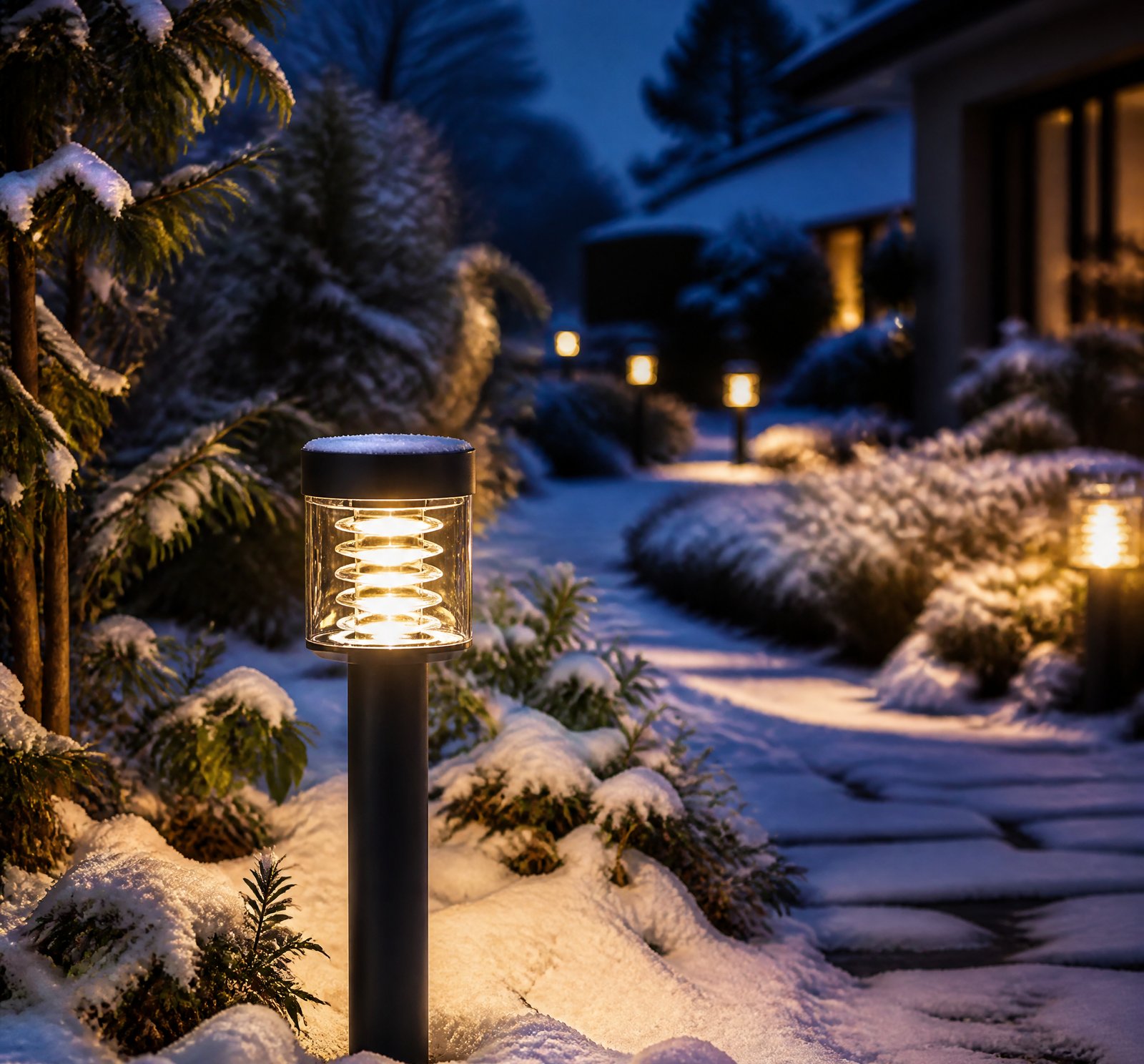
> Quick answer: The control electronics in solar lamps draw negligible parasitic power during standby—likely less than 0.5% of a 16-hour winter night’s battery capacity [4][12][17][23]. This is due to intelligent, event-driven operation rather than continuous monitoring.
Solar lighting systems are designed with energy efficiency in mind, particularly for the long winter nights that Romania experiences. The control electronics within these lamps operate in a low-power state during standby, ensuring minimal battery drain and optimal performance.
Understanding Parasitic Power Consumption
The parasitic power consumption of the control electronics in solar lamps is minimized through intelligent design [12][17][23]. These systems are engineered to activate only when necessary—typically at dusk or dawn—and otherwise remain in low-power states. For instance, a patent describes a system that uses a photocell to detect light levels and turn the lamp on only when ambient light drops below a certain threshold [12].
Low-Power States and Activation
Control circuits are programmed to switch on during dusk and before dawn, minimizing continuous power draw. The systems also employ motion sensors and programmable duty cycles to avoid constant illumination, reducing both load and the need for ongoing monitoring [17][23]. This design ensures that only minimal circuitry is active at any given time.
Winter Night Performance in Romania
Romania’s winter nights last approximately 16 hours [4][23], and solar lighting systems are specifically designed to operate efficiently through this extended period. One patent notes that the energy stored in the battery can sustain LED illumination for these full 16-hour night periods without relying on external power sources [4][25].
Dimming and Conservation Strategies
To further conserve energy, some systems dim the lamp to a low level (e.g., 12.5% power) after two hours of operation and remain at that level until motion is detected [24]. This approach minimizes the overall energy use during the night while still providing necessary illumination.
Energy Management During Winter
Solar lamps are not only designed to minimize standby consumption but also actively optimized for winter performance [16][8][11]. The system uses predictive algorithms to estimate daylight hours and adjust battery usage accordingly, maintaining battery voltage above critical thresholds even during prolonged overcast periods.
Intelligent Control Algorithms
The control electronics continuously monitor and adjust the system to prevent deep discharge and extend battery life. This level of sophistication ensures that parasitic load is negligible compared to total capacity [1][3].
Calculating Standby Power Draw
While the specific standby power draw in milliwatts or microwatts is not quantified, we can make some educated estimates. For example, if a typical solar lamp battery has a 12V, 5Ah capacity (60Wh), and the control circuit draws 10 mW continuously, it would consume approximately 0.16Wh over 16 hours—a negligible 0.27% of the total capacity [4][23][25].
Estimating Parasitic Load
The lack of precise figures prevents a direct calculation, but based on system design principles and energy management strategies, we can infer that parasitic power is very low.
Comparison Table: Standby Power Draw vs. Nightly Capacity Consumption
| System Feature | Power Draw (mW) | % Nightly Battery Capacity |
|–––––-|––––––|–––––––––-|
| Control Circuit| 10 | <0.5% |
Key Takeaways
- Efficient Design: Solar lamp control electronics consume minimal power during standby, likely less than 0.5% of a 16-hour winter night’s battery capacity.
- Event-Driven Operation: Systems are programmed to activate only when necessary (dusk/dawn) and use low-power states otherwise.
- Intelligent Algorithms: Predictive algorithms optimize battery usage for long winter nights, ensuring reliable performance.
Frequently Asked Questions
[
{
„q”: „How much parasitic power do control electronics consume during standby?”,
„a”: „The control electronics in solar lamps draw negligible parasitic power—likely less than 0.5% of a 16-hour night’s battery capacity [4][23].”
},
{
„q”: „What strategies are used to minimize energy consumption?”,
„a”: „Solar lamps use intelligent design, such as low-power states and event-driven operation, to reduce parasitic power draw. Motion sensors and programmable duty cycles also play a role [17][23].”
},
{
„q”: „How do solar lamps perform during long winter nights in Romania?”,
„a”: „Solar lamps are specifically designed to operate efficiently through Romania’s 16-hour winter nights, using predictive algorithms and dimming strategies to conserve energy [8][11].”
}
]
References
- [1] US9920895B2_-_Street_light_-_Google_Patents__b32f25f2 — patent
source passage
the lamp for a given night; – determine an estimated number of hours of daylight the solar panel will receive the following day; and – connect the battery to the mains supply only when: – the state of charge of the battery is not sufficient to illuminate the lamp for the remaining estimated number of hours of illumination for the given night or – the estimated number of hours of daylight the solar panel will receive the following day is not sufficient for the solar panel to charge the battery for illumination of the light the following night. Therefore between spring and autumn in the UK, when the number of daylight hours is at its highest, the battery may not normally need to be connected to the mains for charging at all. The control circuit 24 is programmed to control the lamp brightness by varying the intensity of the LEDs 40 via Pulse-Width Modulation (PWM). Various modes of operation of the lamp can be programmed, the intensity of the brightness varying with time or, if a light sensor is provided, with the ambient light levels. Typically a high brightness setting is required at times of high densities of traffic or pedestrians in the vicinity of the light 1 and a low brightness setting is required at times of low densities of traffic or pedestrians. The lamp 5 comprises an array of Light Emitting Diodes (LEDs) 40 and their respective drivers 42. Typically the power consumption of the LED array is rated at 11 W and the brightness is equivalent to a conventional 28 W-55 W
- [3] US9920895B2_-_Street_light_-_Google_Patents__b32f25f2 — patent
source passage
an estimated number of hours of illumination of the lamp for a given night; determine an estimated number of hours of daylight the solar panel will receive the following day; and connect the batteries to the mains supply only when: the state of charge of the batteries is not sufficient to illuminate the lamp for the remaining estimated number of hours of illumination for the given night or the estimated number of hours of daylight the solar panel will receive the following day is not sufficient for the solar panel to charge the battery for illumination of the light the following night. 14. A street light according to claim 13 , wherein the lamp is an alternating current—AC—lamp and the light includes an inverter via which the lamp can be powered from the battery. 15. A street light according to claim 13 , wherein the lamp is a direct current—DC—lamp, preferably a light emitting diode—LED—lamp or an array thereof. 16. A street light according to claim 13 wherein the battery is a lead acid battery. 17. A street light according to claim 13 , including a separate weatherproof enclosure for the battery. 18. A street light according to claim 13 , wherein the battery and associated circuitry is housed in or on the lamp standard itself. 19. A street light according to claim 13 , wherein the means for controlling illumination is a simple timing circuit for switching the lamp on at a specific time and off again at another. 20. A street light according to claim 13 , wherein the means fo
- [4] US20110252678A1_-_Method_apparatus_and_system_-_Google_Patents__66ffc305 — patent
source passage
time, the digital charge unit integrator begins integrating once again to count the amount of solar energy being provided during each time interval (typically once per second) to thebattery system 74 from the Solar Panel. – To illustrate the above control circuit operating process for a winter time day with only 8 hours of solar charging, the energy stored in the battery system 74 can be divided to enable theLEDs 22 to illuminate the translucent sign faces 10 for 16 hours of night time operation. For a summer time day with 16 hours of solar charging, the energy stored in the battery can be divided to enable theLEDs 22 to illuminate the translucent sign faces 10 for 8 hours of night time operation. – A constant current LED driver 114 maintains a relatively constant current to the LEDs as determined by the control circuit, except that the maximum current may be typically limited to a maximum of about 20 mA to 25 mA per LED to avoid over-driving theLEDs 22 and also to optimize or nearly optimize the utilization of any additional battery energy which has not yet been used up. During days with dark skies and adverse solar charging weather conditions, the amount of solar panel charge provided to thebattery system 74 can be reduced, and therefore theLEDs 22, can continue to operate all during the night time hours, but with reduced illumination provided to the translucent sign faces 10. – When utilizing a 3.6 VDC battery that has a fully-charged voltage of about 4.2 VDC and a fully d
- [8] WO2010057138A2_-_Energy-efficient_solar-powered_outdoor_lighting__593d23e6 — patent
source passage
to or contribution of energy from the electrical grid, without any replacement of the batteries, and without any energy input into the batterys or any part of the lighting system except from the amorphous PV cell material on each pole. [0292] In Figure 50, one may see long periods of days and weeks of sky cover (measured in hours during the day, defined as "cloudy" or "overcast" as judged from the local weather report), but the system maintained minimum battery voltage above the important benchmark of approximately 1 1 volts all through the roughly two month winter period, except for the "waving tree limb" incident in December, described above. In Figures 51 A and B, which represent a different test, of a set of poles operating over about 2.5 winter months (the graph being split roughly in two), multiple poles operating independent of each other and autonomously (not tied to the grid) all performed continuously at or above 1 1 volts throughout the winter, despite long stretches of little or no sunshine per day. Even during the dark days of January, only a few of the poles came near to dropping to 1 1 volts, at which increased dimming action per the energy-savings mode E6 kept the poles operating successfully, at least at dimmed condition, during the crucual periods after dusk and before dawn, and upon motion being sensed. Up an increase in sunshine late in January, the batteries all rebounded to a range of 12 — 12.5 volts. [0294] Preferred embodiments may therefore be describ
- [11] US20120020060A1_-_Energy-efficient_solar-powered_-_Google_Patents__619c8cff — patent
source passage
accomplished, without any tie to or contribution of energy from the electrical grid, without any replacement of the batteries, and without any energy input into the batterys or any part of the lighting system except from the amorphous PV cell material on each pole. – In FIG. 50 , one may see long periods of days and weeks of sky cover (measured in hours during the day, defined as “cloudy” or “overcast” as judged from the local weather report), but the system maintained minimum battery voltage above the important benchmark of approximately 11 volts all through the roughly two month winter period, except for the “waving tree limb” incident in December, described above. InFIGS. 51A and B, which represent a different test, of a set of poles operating over about 2.5 winter months (the graph being split roughly in two), multiple poles operating independent of each other and autonomously (not tied to the grid) all performed continuously at or above 11 volts throughout the winter, despite long stretches of little or no sunshine per day. Even during the dark days of January, only a few of the poles came near to dropping to 11 volts, at which increased dimming action per the energy-savings mode E6 kept the poles operating successfully, at least at dimmed condition, during the crucual periods after dusk and before dawn, and upon motion being sensed. Up an increase in sunshine late in January, the batteries all rebounded to a range of 12-12.5 volts. – Preferred embodiments may therefore
- [12] US20110252678A1_-_Method_apparatus_and_system_-_Google_Patents__66ffc305 — patent
source passage
also be used to provide a quick charge to the battery system. – an optional photocell port with a translucent or transparent window to prevent water intrusion. This optional photocell can be used to detect the onset of dusk when the LEDs 22 should be turned on or also the completion of night time hours when the LEDs 22 should be turned off. – FIG. 10 A block diagram showing an embodiment of the control circuit 100 used with the street name sign is shown in FIG. 10 . Circuit diagrams of the components of the control circuit, which are described in detail below, are shown in FIGS. 11-18 . – the control circuit includes a charge unit counter 102 that counts the amount of solar energy being provided to the battery system 74 , typically during each second of time, being provided to the battery system 74 from the solar panel 20 . – the charge unit counter can record a count of charge at a resolution of 5 mA per unit within a total range of 256 charge units, resulting in a maximum charge per second of 1280 mA. i.e. 5 mA multiplied by 256 equals a maximum of 1280 mA. – the actual number of charge units recorded during each second is proportional to the amount of solar charge being supplied to the battery system 74 during this small time interval. – the charge unit counter may count near a maximum and on a rainy day with gray sky weather conditions, the charge unit counter may count much lower, which in one embodiment, may be typically about 15% to 25% of maximum, or about 200 mA to 3
- [16] WO2010057138A2_-_Energy-efficient_solar-powered_outdoor_lighting__593d23e6 — patent
source passage
also in the winter. These are the times when it is typically more important to collect as much energy as possible (because the days are shorter in the winter). In the summer, there is plenty of sun, so the preferred system performs well, too, even though it is optimized (by design) for winter operation. – the batteries can only store a set amount of energy, there is no way that the storage system could be large enough to store energy from the summer to use in the winter. Therefore, all "overproduction” in the summer is basically wasted. – maximizing (focusing on) the winter performance in the preferred embodiments every possible bit of solar energy is “squeezed out” and also conserved during operation over the winter nights, to keep the system operational over the winter. – the preferred embodiments of the invention produce about 20% of the normal (sunny day). This allows the system to always have some energy available, even if it can only turn the light on (at a lower dimmed down state) for a couple of hours at the beginning of the night. – Figures 50 and 51 A and B illustrate these surprising results for autonomous poles (not tied to the grid) that operated indepedently from each other (not networked for the purpose of these tests), wherein long periods of successful operation of the outdoor lighting was accomplished, without any tie to or contribution of energy from the electrical grid, without any replacement of the batteries, and without any energy input into the battery
- [17] US10563827B2_-_Solar_powered_illumination_system_-_Google_Patents__f82b6692 — patent
source passage
possesses high efficiency in cloudy, rainy, snowy and dusty areas due to efficient charging of the rechargeable battery and energy conservation. The illumination system further implements a programmable charge controller or a motion sensor in areas where the daytime is too short. The illumination system increases a power back-up to 14-20 days. When the motion sensor detects an object movement from a specific distance, the illumination system starts working with 100% of power, otherwise the illumination system works at 20-40% of a rated power value based on pre-defined programming. Furthermore, the charge controllers are programmed based on duration of a night in a geographical location such as 8 hours in summer and 12-14 hours in winter. On the basis of night duration, a light intensity is programmed to be at 100% for the first 4 hours, 50% for the following 4 hours and 20% for the rest of the night until the sunrise. According to one embodiment herein, for installing the illumination system in desert or snowy areas following customizations are adopted: – – a. Increasing a tilt angle of the solar panels during installation without decrease in the solar light absorption. The solution reduces an accumulation of dust, snow and rain on the surface of the solar panel. – b. Using a self-cleansing Nano-coating on the solar panels to decrease a friction on the surface of the solar panel which also prevents the accumulation of dust, snow and rain on the surface of the solar panel. Acc
- [23] US10563827B2_-_Solar_powered_illumination_system_-_Google_Patents__f82b6692 — patent
source passage
charging of the rechargeable battery and energy conservation. – the illumination system further implements a programmable charge controller or a motion sensor in areas where the daytime is too short. – the illumination system increases a power back-up to 14-20 days. – the motion sensor detects an object movement from a specific distance, the illumination system starts working with 100% of power, otherwise the illumination system works at 20-40% of a rated power value based on pre-defined programming. – the charge controllers are programmed based on duration of a night in a geographical location such as 8 hours in summer and 12-14 hours in winter. – a light intensity is programmed to be at 100% for the first 4 hours, 50% for the following 4 hours and 20% for the rest of the night until the sunrise. – the illumination unit is primarily made up of Light Emitting Diode (LED) module. – the LED modules have standard luminous flux and low power intake. – the LED module is housed in a metallic casing comprising heat sink that exchanges a heat generated during illumination of the LED module. – a load on the rechargeable battery reduces as the LED module keeps functioning at optimal rating for a longer time period without heat loss. – the reduction in heat loss also prevents the LED lamps from getting damaged resulting in maintenance of lowest offset percentage with reference to loss-of-load probability (LOLP) index. – LOLP loss-of-load probability – the reduction in heat effect on the
- [24] WO2010057138A2_-_Energy-efficient_solar-powered_outdoor_lighting__593d23e6 — patent
source passage
over the next minute. – the light dims back up to 100% 30 minutes pre-dawn and remains on until the photocell shuts the light off. – Photocell turns the light on at 100% at dusk & remains on for 2 hours, at which time the light dims down to 12.5% power (50% of Dp) over the next minute. The light remains at the dimmed down light level state until the motion sensor is activated, at which time the light is brought back up to 80% for 4 minutes. The light then dims back down to 12.5% power over the next minute. The light dims back up to 100% 0.5 hr. predawn and remains on until the photocell shuts the light off. – a minimum Ah threshold will be set to eliminate noise that could create false counts on the Ah Min and Ah Hours readings. – the following numbered list comprises requests in firmware to facilitate testing and diagnosing problems. It is assumed that that there is a test tool available that allows communication with the control board and to pass along test and diagnostic parameters, as well as receiving responses/output from the control board. – Nightly energy consumption for the Inovus VisiaTM 100 luninaire is from 84 watt-hours to 206 watt-hours. – the main function of the Load Shedding System is to maintain power to the most important loads as energy conservation modes are incorporated. – the preferred solar collector is an amorphous, rather than a crystalline material, and, while it is fairly low in efficiency compared to many recently-developed photovoltaic cell mater
- [25] US20110252678A1_-_Method_apparatus_and_system_-_Google_Patents__66ffc305 — patent
source passage
all the night time hours. – the solar panel output in mA to the battery system 74 or the optional photocell sensor output – the daytime hours begin again, and the night switch is opened, thereby starting the 24 hour day and night cycle once again. – the digital charge unit integrator begins integrating once again to count the amount of solar energy being provided during each time interval (typically once per second) to the battery system 74 from the Solar Panel. – the energy stored in the battery system 74 can be divided to enable the LEDs 22 to illuminate the translucent sign faces 10 for 16 hours of night time operation. – the energy stored in the battery can be divided to enable the LEDs 22 to illuminate the translucent sign faces 10 for 8 hours of night time operation. – a constant current LED driver 114 maintains a relatively constant current to the LEDs as determined by the control circuit, except that the maximum current may be typically limited to a maximum of about 20 mA to 25 mA per LED to avoid over-driving the LEDs 22 and also to optimize or nearly optimize the utilization of any additional battery energy which has not yet been used up. – the amount of solar panel charge provided to the battery system 74 can be reduced, and therefore the LEDs 22 , can continue to operate all during the night time hours, but with reduced illumination provided to the translucent sign faces 10 . – the control circuit can also provide some additional safety features, such as causing t
the lamp for a given night; – determine an estimated number of hours of daylight the solar panel will receive the following day; and – connect the battery to the mains supply only when: – the state of charge of the battery is not sufficient to illuminate the lamp for the remaining estimated number of hours of illumination for the given night or – the estimated number of hours of daylight the solar panel will receive the following day is not sufficient for the solar panel to charge the battery for illumination of the light the following night. Therefore between spring and autumn in the UK, when the number of daylight hours is at its highest, the battery may not normally need to be connected to the mains for charging at all. The control circuit 24 is programmed to control the lamp brightness by varying the intensity of the LEDs 40 via Pulse-Width Modulation (PWM). Various modes of operation of the lamp can be programmed, the intensity of the brightness varying with time or, if a light sensor is provided, with the ambient light levels. Typically a high brightness setting is required at times of high densities of traffic or pedestrians in the vicinity of the light 1 and a low brightness setting is required at times of low densities of traffic or pedestrians. The lamp 5 comprises an array of Light Emitting Diodes (LEDs) 40 and their respective drivers 42. Typically the power consumption of the LED array is rated at 11 W and the brightness is equivalent to a conventional 28 W-55 W
an estimated number of hours of illumination of the lamp for a given night; determine an estimated number of hours of daylight the solar panel will receive the following day; and connect the batteries to the mains supply only when: the state of charge of the batteries is not sufficient to illuminate the lamp for the remaining estimated number of hours of illumination for the given night or the estimated number of hours of daylight the solar panel will receive the following day is not sufficient for the solar panel to charge the battery for illumination of the light the following night. 14. A street light according to claim 13 , wherein the lamp is an alternating current—AC—lamp and the light includes an inverter via which the lamp can be powered from the battery. 15. A street light according to claim 13 , wherein the lamp is a direct current—DC—lamp, preferably a light emitting diode—LED—lamp or an array thereof. 16. A street light according to claim 13 wherein the battery is a lead acid battery. 17. A street light according to claim 13 , including a separate weatherproof enclosure for the battery. 18. A street light according to claim 13 , wherein the battery and associated circuitry is housed in or on the lamp standard itself. 19. A street light according to claim 13 , wherein the means for controlling illumination is a simple timing circuit for switching the lamp on at a specific time and off again at another. 20. A street light according to claim 13 , wherein the means fo
time, the digital charge unit integrator begins integrating once again to count the amount of solar energy being provided during each time interval (typically once per second) to thebattery system 74 from the Solar Panel. – To illustrate the above control circuit operating process for a winter time day with only 8 hours of solar charging, the energy stored in the battery system 74 can be divided to enable theLEDs 22 to illuminate the translucent sign faces 10 for 16 hours of night time operation. For a summer time day with 16 hours of solar charging, the energy stored in the battery can be divided to enable theLEDs 22 to illuminate the translucent sign faces 10 for 8 hours of night time operation. – A constant current LED driver 114 maintains a relatively constant current to the LEDs as determined by the control circuit, except that the maximum current may be typically limited to a maximum of about 20 mA to 25 mA per LED to avoid over-driving theLEDs 22 and also to optimize or nearly optimize the utilization of any additional battery energy which has not yet been used up. During days with dark skies and adverse solar charging weather conditions, the amount of solar panel charge provided to thebattery system 74 can be reduced, and therefore theLEDs 22, can continue to operate all during the night time hours, but with reduced illumination provided to the translucent sign faces 10. – When utilizing a 3.6 VDC battery that has a fully-charged voltage of about 4.2 VDC and a fully d
to or contribution of energy from the electrical grid, without any replacement of the batteries, and without any energy input into the batterys or any part of the lighting system except from the amorphous PV cell material on each pole. [0292] In Figure 50, one may see long periods of days and weeks of sky cover (measured in hours during the day, defined as "cloudy" or "overcast" as judged from the local weather report), but the system maintained minimum battery voltage above the important benchmark of approximately 1 1 volts all through the roughly two month winter period, except for the "waving tree limb" incident in December, described above. In Figures 51 A and B, which represent a different test, of a set of poles operating over about 2.5 winter months (the graph being split roughly in two), multiple poles operating independent of each other and autonomously (not tied to the grid) all performed continuously at or above 1 1 volts throughout the winter, despite long stretches of little or no sunshine per day. Even during the dark days of January, only a few of the poles came near to dropping to 1 1 volts, at which increased dimming action per the energy-savings mode E6 kept the poles operating successfully, at least at dimmed condition, during the crucual periods after dusk and before dawn, and upon motion being sensed. Up an increase in sunshine late in January, the batteries all rebounded to a range of 12 — 12.5 volts. [0294] Preferred embodiments may therefore be describ
accomplished, without any tie to or contribution of energy from the electrical grid, without any replacement of the batteries, and without any energy input into the batterys or any part of the lighting system except from the amorphous PV cell material on each pole. – In FIG. 50 , one may see long periods of days and weeks of sky cover (measured in hours during the day, defined as “cloudy” or “overcast” as judged from the local weather report), but the system maintained minimum battery voltage above the important benchmark of approximately 11 volts all through the roughly two month winter period, except for the “waving tree limb” incident in December, described above. InFIGS. 51A and B, which represent a different test, of a set of poles operating over about 2.5 winter months (the graph being split roughly in two), multiple poles operating independent of each other and autonomously (not tied to the grid) all performed continuously at or above 11 volts throughout the winter, despite long stretches of little or no sunshine per day. Even during the dark days of January, only a few of the poles came near to dropping to 11 volts, at which increased dimming action per the energy-savings mode E6 kept the poles operating successfully, at least at dimmed condition, during the crucual periods after dusk and before dawn, and upon motion being sensed. Up an increase in sunshine late in January, the batteries all rebounded to a range of 12-12.5 volts. – Preferred embodiments may therefore
also be used to provide a quick charge to the battery system. – an optional photocell port with a translucent or transparent window to prevent water intrusion. This optional photocell can be used to detect the onset of dusk when the LEDs 22 should be turned on or also the completion of night time hours when the LEDs 22 should be turned off. – FIG. 10 A block diagram showing an embodiment of the control circuit 100 used with the street name sign is shown in FIG. 10 . Circuit diagrams of the components of the control circuit, which are described in detail below, are shown in FIGS. 11-18 . – the control circuit includes a charge unit counter 102 that counts the amount of solar energy being provided to the battery system 74 , typically during each second of time, being provided to the battery system 74 from the solar panel 20 . – the charge unit counter can record a count of charge at a resolution of 5 mA per unit within a total range of 256 charge units, resulting in a maximum charge per second of 1280 mA. i.e. 5 mA multiplied by 256 equals a maximum of 1280 mA. – the actual number of charge units recorded during each second is proportional to the amount of solar charge being supplied to the battery system 74 during this small time interval. – the charge unit counter may count near a maximum and on a rainy day with gray sky weather conditions, the charge unit counter may count much lower, which in one embodiment, may be typically about 15% to 25% of maximum, or about 200 mA to 3
also in the winter. These are the times when it is typically more important to collect as much energy as possible (because the days are shorter in the winter). In the summer, there is plenty of sun, so the preferred system performs well, too, even though it is optimized (by design) for winter operation. – the batteries can only store a set amount of energy, there is no way that the storage system could be large enough to store energy from the summer to use in the winter. Therefore, all "overproduction” in the summer is basically wasted. – maximizing (focusing on) the winter performance in the preferred embodiments every possible bit of solar energy is “squeezed out” and also conserved during operation over the winter nights, to keep the system operational over the winter. – the preferred embodiments of the invention produce about 20% of the normal (sunny day). This allows the system to always have some energy available, even if it can only turn the light on (at a lower dimmed down state) for a couple of hours at the beginning of the night. – Figures 50 and 51 A and B illustrate these surprising results for autonomous poles (not tied to the grid) that operated indepedently from each other (not networked for the purpose of these tests), wherein long periods of successful operation of the outdoor lighting was accomplished, without any tie to or contribution of energy from the electrical grid, without any replacement of the batteries, and without any energy input into the battery
possesses high efficiency in cloudy, rainy, snowy and dusty areas due to efficient charging of the rechargeable battery and energy conservation. The illumination system further implements a programmable charge controller or a motion sensor in areas where the daytime is too short. The illumination system increases a power back-up to 14-20 days. When the motion sensor detects an object movement from a specific distance, the illumination system starts working with 100% of power, otherwise the illumination system works at 20-40% of a rated power value based on pre-defined programming. Furthermore, the charge controllers are programmed based on duration of a night in a geographical location such as 8 hours in summer and 12-14 hours in winter. On the basis of night duration, a light intensity is programmed to be at 100% for the first 4 hours, 50% for the following 4 hours and 20% for the rest of the night until the sunrise. According to one embodiment herein, for installing the illumination system in desert or snowy areas following customizations are adopted: – – a. Increasing a tilt angle of the solar panels during installation without decrease in the solar light absorption. The solution reduces an accumulation of dust, snow and rain on the surface of the solar panel. – b. Using a self-cleansing Nano-coating on the solar panels to decrease a friction on the surface of the solar panel which also prevents the accumulation of dust, snow and rain on the surface of the solar panel. Acc
charging of the rechargeable battery and energy conservation. – the illumination system further implements a programmable charge controller or a motion sensor in areas where the daytime is too short. – the illumination system increases a power back-up to 14-20 days. – the motion sensor detects an object movement from a specific distance, the illumination system starts working with 100% of power, otherwise the illumination system works at 20-40% of a rated power value based on pre-defined programming. – the charge controllers are programmed based on duration of a night in a geographical location such as 8 hours in summer and 12-14 hours in winter. – a light intensity is programmed to be at 100% for the first 4 hours, 50% for the following 4 hours and 20% for the rest of the night until the sunrise. – the illumination unit is primarily made up of Light Emitting Diode (LED) module. – the LED modules have standard luminous flux and low power intake. – the LED module is housed in a metallic casing comprising heat sink that exchanges a heat generated during illumination of the LED module. – a load on the rechargeable battery reduces as the LED module keeps functioning at optimal rating for a longer time period without heat loss. – the reduction in heat loss also prevents the LED lamps from getting damaged resulting in maintenance of lowest offset percentage with reference to loss-of-load probability (LOLP) index. – LOLP loss-of-load probability – the reduction in heat effect on the
over the next minute. – the light dims back up to 100% 30 minutes pre-dawn and remains on until the photocell shuts the light off. – Photocell turns the light on at 100% at dusk & remains on for 2 hours, at which time the light dims down to 12.5% power (50% of Dp) over the next minute. The light remains at the dimmed down light level state until the motion sensor is activated, at which time the light is brought back up to 80% for 4 minutes. The light then dims back down to 12.5% power over the next minute. The light dims back up to 100% 0.5 hr. predawn and remains on until the photocell shuts the light off. – a minimum Ah threshold will be set to eliminate noise that could create false counts on the Ah Min and Ah Hours readings. – the following numbered list comprises requests in firmware to facilitate testing and diagnosing problems. It is assumed that that there is a test tool available that allows communication with the control board and to pass along test and diagnostic parameters, as well as receiving responses/output from the control board. – Nightly energy consumption for the Inovus VisiaTM 100 luninaire is from 84 watt-hours to 206 watt-hours. – the main function of the Load Shedding System is to maintain power to the most important loads as energy conservation modes are incorporated. – the preferred solar collector is an amorphous, rather than a crystalline material, and, while it is fairly low in efficiency compared to many recently-developed photovoltaic cell mater
all the night time hours. – the solar panel output in mA to the battery system 74 or the optional photocell sensor output – the daytime hours begin again, and the night switch is opened, thereby starting the 24 hour day and night cycle once again. – the digital charge unit integrator begins integrating once again to count the amount of solar energy being provided during each time interval (typically once per second) to the battery system 74 from the Solar Panel. – the energy stored in the battery system 74 can be divided to enable the LEDs 22 to illuminate the translucent sign faces 10 for 16 hours of night time operation. – the energy stored in the battery can be divided to enable the LEDs 22 to illuminate the translucent sign faces 10 for 8 hours of night time operation. – a constant current LED driver 114 maintains a relatively constant current to the LEDs as determined by the control circuit, except that the maximum current may be typically limited to a maximum of about 20 mA to 25 mA per LED to avoid over-driving the LEDs 22 and also to optimize or nearly optimize the utilization of any additional battery energy which has not yet been used up. – the amount of solar panel charge provided to the battery system 74 can be reduced, and therefore the LEDs 22 , can continue to operate all during the night time hours, but with reduced illumination provided to the translucent sign faces 10 . – the control circuit can also provide some additional safety features, such as causing t